When you think of simple synths, what components come to mind? All you really need to make one is an oscillator, an amplifier, and some kind of input such that you can play different notes. Our favorite go-to for churning out square waves is probably the 40106 IC, which has six inverting Schmitt triggers, and then usually a 386 to amplify the output.
But it’s possible to go even simpler than that, and school is in session with [Jule] giving the lesson. [Jule]’s little analog synth uses a single IC for both the oscillator and the amplifier — a TL072 op-amp. The rest is made of purely discrete components.
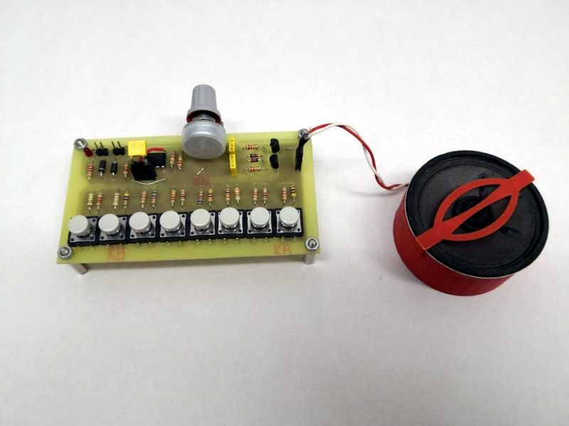
[Jule] says those momentary switches are sub-par, and will add a vibrato effect if properly wiggled while pressed. To us, the buttons looks pretty nice, and much easier to jam out with than the ones with 1/8″ diameter actuators. Plus, whenever you press multiple buttons, the additive resistance unlocks the synth’s inner R2D2 voice. We really see no downsides here.
By default, this is an eight-button synth tuned to C major. But there’s a surprise — you can plug different capacitors into a piece of header and change the octave on the fly. Check it out after the break.
Making pitch-correct frequencies requires weird resistor values, which we can usually satisfy with two resistors in series. But wait, what’s up with resistor values, anyway? And why do they have a color code?


I’m sorry but they are supposed to be instruments. If you can’t produce a physically exciting response from it, it ain’t a synth.
Madonna uses many many synthesizers in her music and yet somehow fails to produce any sort of physically exciting response. In fact fans are known to leave her shows early and ask for refunds. Are you going to deny that the uses synthsizers or what???
Well, your obvious poor attempt sarcasm and scorn for Madonna aside….
He said if you can’t produce a physically exciting response from it, it ain’t a synth. That in no way means every sound you produce from a synth is magically automatically physically exciting.
You’ve made the logical fallacy of confusing a sufficient condition with a necessary one.
Tell that to Kraftwerk
I think this would be called an organ. I tried making one in 1971, with keys made from strips cut from tin cans. I think transistors in tge oscillator, but many organ projects back then used unijunction transistors and a few years later a 555.
A synthesizer is to synthesize instruments, or sounds. So you need an oscillator that can generate various waveforms. Some filtering, maybe dynamic. A voltage controlled amplifier, and an envelope generator to control it. Add other modules as needed.
Synthesizers weren’t originally designed to “play music”. They were bulky and good to play ne note at a time, so often you coukd only hear music if you did a lot of work into a tape recorder.
If you look at live concert footage from the 1970s you can see quite readily that the “one note at a time” issue for live music is easily overcome with multiple synthesizers. Check out photos of bands like ELP and YES, the keyboard players are sometimes surrounded by synthesizers.
The 1970 MiniMoog was portable and designed to take on tour for live performances, just about everyone.who went to a concert in the 1970s was listening to live synthesized music with no tape recorders involved.
An organ is an instrument made up of pipes, reeds or electronic devices of fixed pitch all of which operate independently. This has only one variable pitch device and therefore is more likely to be called a solovox.
So where is this “MacGuyver” thing coming from?
I dunno, but maybe you could make a capacitor with some tinfoil and get it to make free phone calls in the 1980s?
I’d have at least hoped to see a protoboard with jumper wires instead of a PCB.
Or at least those Radio Shack 150-in-1 springs.
That would have been MacGyver. Don’t know where she was going with MacGuyver
The article claims the chip is serving as the amplifier but this is completely untrue, showing either dishonesty of lack of understanding. 1/2 of it is used as a unity gain buffer which could have also been supplied by a single bootstrapped NPN or a single JFET. The amplifier is a classic 2 transistor output stage from the 1960s. A 555 organ from 1975 drives a speaker directly without any additional chips and does the same thing this project does. MacGyver? No, not even slightly.
This is not a “cool synthesizer”, this is just an ic oscillator.
No Raspi, no Arduino, no 555, this thing has nothing to do on HaD.
I think you’re mistaking HaD for RA5aD.
Discrete circuit built on a home-etched board making audio in well documented writeup along with video. Geez, I’m happy to read about projects like this one.
Yeah, technically it’s a triangle wave organ.
One opamp is the triangle generator (not an amp) the other opamp is a buffer (not an amp) and the transistors are drivers with no voltage gain (not an amp).
In any case, if they want to move on to a more complex analog synth then they’re already on the right path with opamps.
Opamps can: Amp, derive, integrate, Voltage to frequency, voltage to gain, voltage to current and all the converse functions.
Tip: you can make a complex circuit with a number of opamps and passives. Then you can calculate the passives collectively as a network and then place the resulting passives around ONE opamp to get the same result. Most high gain , high slew rate opamps can do this, even a retro old TL072, we did it back then.
It’s great to see someone nutting our analog.
Older people take analog for granted but today it’s still really useful for things like this and signal conditioning for uc etc.
It’s by the most part a shamefully lost skill.
If you want to make a synth, op-amps as function generators aren’t exactly ideal because they don’t switch between states very well. They are designed to work in the linear region, not in the saturation region, so the output “clamps” to the rails for some time every time they change state, and that makes the frequency response non-linear above a couple kilohertz. Likewise, if you’re using an integrator to make ramps, the input leakage current messes up the results at the low end. It doesn’t stay in tune across different octaves.
_The_ classic analog (sawtooth/triangle) synth core is an integrating op-amp. (http://www.synthsource.com/ens76/vco.html)
(BTW: http://electronotes.netfirms.com/free.htm)
But you’re right about switching speed: good ones use something faster as a comparator, like a comparator. Which is really just an op-amp tuned to switch fast at threshold.
Leakage current can also be compensated and tuned out.
How else would you design an analog VCO other than with op-amps, though? All the “serious” VCOs I’ve seen are full of ’em.
More precisely: an op-amp is a comparator with a push-pull output stage tuned for linear response.
>How else would you design an analog VCO
Relaxation oscillators and constant current drivers were the first kind to be used, but they produce sawtooth-like waveforms so they were used in subtractive synths with a bunch of filters and harmonic resonators. The sound by itself without filtering is like torturing a cat, but with a bunch of filters it creates the strange sounds of the early synths. See for example, the Mixtur-Trautonium.
Op-amps and integrators enabled the generation of clean waveforms with simple harmonics, so they were used for additive synths.
Check this out (Falstad link): http://tinyurl.com/ucg7lcc
These are design issues.
Modern opamps have an offset of a small number of picoamps.
Yeah, good ones, but it’s still a better idea to implement the comparators as comparators instead of op-amps because they’re just faster. In fact you might even build a bare differential pair to have the least amount of propagation delay.
If you don’t have reliable instant switching, you will have issues controlling the amplitude of the waveform and the frequency control goes to hell with it.
In fact, one cheap way to do it is to use the dreaded 555 as a schmitt-trigger with built-in hysteresis, since it has two comparators inside. The control voltage input fixes the upper level, and the lower level will be half of that. If you pick a fast CMOS part, it automatically gives you a well defined amplitude and fixes the signal to a known reference.
555s (and 556) make very good VCOs as they can run from sub Hz right through or hearing range.
For symmetrical wave forms like saw at the comparator side and square at the flipflop side … The square wave can integrated to a saw and the saw can be integrated to a sine.
These become even more interesting when you use a non symmetrical wave source.
Yes, though one of the disadvantages of modifying square waves is that the amplitude becomes frequency dependent. A sawtooth is easier for a start, but in order to have a good approximation of a sine, you have to rectify the saw into a triangle wave first. It’s less complicated to generate a triangle wave to begin with.
And, instead or passing the triangle through an integrator, which would again make the amplitude dependent on the frequency, you pass it through a logarithmic amplifier. Basically an inverting op-amp with two diodes in the feedback loop. The amplifier “saturates” smoothly, so it rounds off the triangle wave and you can vary the waveform continuously from a triangle through a sine to a square wave.
Also a buffer or “driver” is an amp: Even without voltage gain, it gives you current gain and thus power gain. So it is an amplifier.
In RF it’s sometimes the opposite way: power transistors are even used in “common base” connection without any current gain (the input is the emitter), so they give only voltage gain. This is just a question of proper impedance matching.
I wonder when they’re going to start offering “buzzkill ratings” for comment threads. I’d give this one 4 and a half stars
I’m with Norm!
Who pissed in y’alls’ Wheaties?
Well…the project is a trifle underwhelming, technically and soundwise. Even in the project video, the maker is playing up the cheese factor. And the write-up’s “MacGyver” framing is off the mark. I don’t ever recall Mac making a PCB for anything…
Back in the day, the magazines could be counted on for one or two of these simple organs a year, so we olds are perhaps still a bit jaded. I suppose it is useful for the young’uns to see this technique for oscillation, and it is capable of a few useful noises. If you manage to tune it.
Finally, let’s not forget that the 8-note C major octave is the epitome of white (key) privilege ;-P
Well I’m an old fart to.
As I said in another post, oldies take analog for granted.
Younger people are not taught analog very well.
The truth is that digital didn’t completely replace analog.
I’ve seen many microcontroller designs where half the CPU resources are consumed for signal conditioning because things didn’t work as expected.
Fix it in software, just ask Boeing.
In most cases just a very small number of passives could have fixed the problem before it was even a problem.
You can’t run before you can walk.
It’s great to see simple analog projects that would encourage others to learn a very useful but old technology.
For a synth, it would’ve been more interesting to have a VCO…
– That generates saw wave (other waveforms can be created from saw)
– That generates a stable pitch (low temperature drift)
– That has a nicely predictable exponential or linear frequency scale
– That isn’t phase locked to a digital OSC
– That can easily be controlled from a CPU
Then again, the goal here was to use few components and be conceptually simple, and explain the general concepts behind oscillators and not go into complex designs, so I guess that is okay.
You don’t need that many components for that kind of “synth”, just a single UJT and an other BJT:
http://www.aaroncake.net/Circuits/torgan.gif
I’ll dig out my book about the PAIA Gnome for you. Ah, there it is, the “electronic music circuit guidebook” by Brice Ward. You might find a copy in PDF somewhere on the ‘net.