Even the oldest of mechanisms remain useful in modern technology. [Skyentific] has been messing with robotic joints for quite a while, and demonstrated an interesting way to use a pulley system in a robotic joint with quite a bit of mechanical advantage and zero backlash.
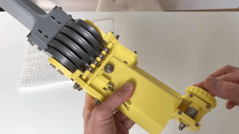
Inspired by the LIMS2-AMBIDEX robotic arm, the mechanism is effectively two counteracting sets of pulley, running of the same cable reel, with rollers allowing them to act around the bend of the joint. Increasing the mechanical advantage of the joint is simply a matter of adding pulleys and rollers. If this is difficult to envision, don’t work as [Skyentific] does an excellent job of explaining how the mechanism works using CAD models in the video below.
The mechanism is back drivable, which would allow it to be used for dynamic control using a motor with an encoder for position feedback. This could be a useful feature in walking robots that need to respond to dynamically changing terrain to stay upright, or in arms that need to push or pull without damaging anything. With properly tensioned cables, there is no backlash in the mechanism. Unfortunately cables can stretch over time, so it is something that needs to be considered when using this in a project.
Pulley systems have been with us for a very long time, and remain a very handy tool to have in your mechanical toolbox. A similar arrangement is used in the Da Vinci surgical robots to control their tiny manipulators. It would also be interesting to see this used in the already impressive robots of [James Bruton].


Cables stretching either through plastic or elastic deformation can be counteracted by using an encoder to complete a servomechanism.
Won’t the output (the angle of the joint) be a nonlinear function of the input rotation? The cable angle changes as it winds and unwinds from the drum. This wouldn’t be an issue if there’s a positional encoder on the joint and the mechanism is driven with a control loop, but it might be a problem for an open loop system, or a system in which only the input position/rotation is driven in a control loop.
The tension on the cable will also change as the position of the joint changes.
You might be surprised on both points (nonlinearity and tension). Note the takeup also goes the same but opposite way, so it’s a second order effect on an already small angle. So go ahead and work it out: how many encoder bits do you need to reliably detect and correct the nonlinearity?
Looking at the design, it should be possible to chain another joint past this one, and thread it’s cable over another large pulley at the previous joint, and back to the base.
Should be able to keep all the low backlash advantages, and keep the weight of the motors at the base
If I remember right, the Phantom Omni robot arm uses this sort of drive, too. It’s a very good type of drive for haptic feedback devices. I worked with one before, and in combination with a 3D visualization on a computer it can deliver some very realistic feedback for “touching” virtual objects.
> zero backlash
I don’t think this is possible in this context.
(having not watched the video), I think it means there’s no movement deadzone due to movement clearances (such as the depthing of gears with a little bit of slack in the output side with a locked input. some CD drives have a backlash-uptake gear consisting of two half-thickness gears with a spring preloading them with scissoring torque, which retains the free space between gears while eliminating the space between the teeth
Its actually better – which no slop between directions it really can be considered backlash free but its also capable of great accuracy and simple!
At least from the motor shaft all the way though the reduction stages to the final motion there is no free wobble movement as between gear teeth – if the cables are pretensioned enough there won’t be any meaningful trouble there either – cable stretch far more initially at low tensions and can be so overspeced for the loads the motor can move you are talking nanometers of extension beyond the intended movement. The only slop in the system overall is the steps in the motor coils and manufacturing tolerances with play in the bearings etc (though the drum winding could introduce inaccuracies proper design mitigates that and it will be rather repeatable so can then further be eliminated in software afterwards.
it reminds me of GUS simpson. The non linearity was resolved very well in that mechanism . Sadly it was a PITA to calibrate.
https://www.youtube.com/watch?v=IEGTe1G2Gqs
https://www.youtube.com/watch?v=pI-LRLJDipk
That video might make you ill, image stabilisation software had its fun.
Instead of all the cables around the joint, a metal band/strip could be used to do only one half a turn and the cables and small pulleys would act on the ends of the metal strip. In that way all the cables would ride on a flat surface.
Good idea, but I’m afraid the steel wire rope will fatigue quickly, with such small bending radii on the small pulleys. Try a Kevlar braid…
Where does one purchase the cabling that was used for this robot arm. I have a similar project I’m working on. Thanks!