We’re pretty familiar with budget resistor-based bend sensors at this point, but this sensor is in a totally different class. Instead of relying on resistive elements, [Useok Jeong] and [Kyu-Jin Cho] devised a bend sensor that relies on geometric properties of the sensor itself. The result is a higher-fidelity measuring device made from a pretty widely available collection of stock parts.
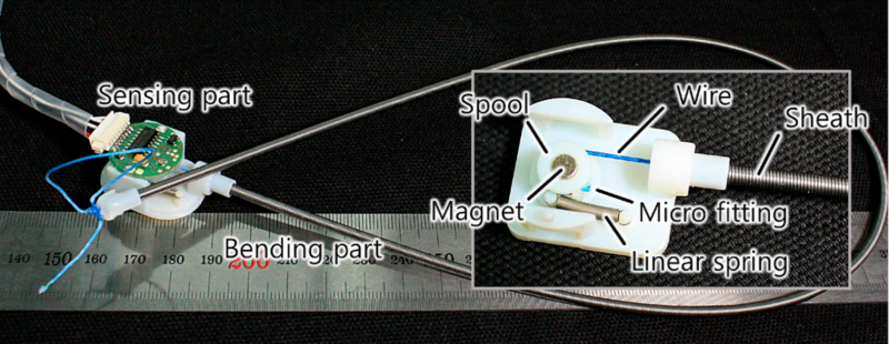
We’ll admit, calling this device a bend sensor might be a bit of a stretch, so let’s dig into some of the operating principles. What we’re actually measuring is the accumulated angle, the sum of all the curvature deformations along the length of the sensing element. The sensor is made of 3 main pieces: an outer extension spring-based wire sheath; a flexible, tensioned inner wire core that’s fixed at one end; and a small displacement sensor that measures the length changes in the wire’s free end. The secret ingredient to making this setup work is a special property of the outer wire sheath or spring guide. Here, the spring guide actually resists being compressed while being bent. Because the inner radius of the bend remains a constant length, the center wire core is forced to elongate. With the excess wire spooled up at the sensor base, we simply measure how much we collected, apply some math, and get a resulting angle! What’s more, the folks behind this trick also demonstrate that the length and angle relationship is linear with an R-square of 0.9969.
One of the best parts about this sensor is how reproducible it seems from from a modest collection of stock parts. Spring guide (aka: extension spring) is available from McMaster-Carr and DR Templeman, and that flexible core might be readily substituted with some wire rope.
It’s not everyday that new topologies for bend sensors pop into the world, let alone linear ones. To learn more, the folks behind the project have kindly made their research paper open access for your afternoon reading enjoyment. (Bring scratch paper!) Finally, if you’re looking for other bend-related sensors, have a look at this multi-bend measurement setup.


This appears to be using a long-known issue with bicycle brake cables, and the one that the SIS cables were designed to eliminate.
Traditional bicycle brakes (and all control cables of the Bowden type) use a coiled spring outer and a wire cable inner.
When used for bar-mounted gear shifters this was found to lead to phantom shifts when turning the bars (this was one reason that the shifters were traditionally on the downtube) . As gear counts increased and the travel ratios decreased this became a real problem, and Shimano (I think) created the SIS cable outer which is a bundle of longitudinal wires held together by a plastic sheath. This doesn’t have the “spring opening on the outside” issue that this sensor is utilising.
The drawback is that SIS cable is nothing like as strong, and if the gear mechanisms become stiff you can have the bundle burst apart, or pull all the wires through the end-ferrule. So it really won’t work for brakes. Luckily brakes are force-modulated so you don’t particularly notice the effect and coiled-wire sheaths are used.
So, it was always the case that if you mix up the sheaths your brakes might fail, but now also if you mix up the sheaths your bend sensor might not work.
I like the idea of using a bowden cable as bend sensor, but had to search around for how the movement of the cable is translated into some electrical value.
Page 13 has some details about the sensor part. The inner cable is wound around a diametrically polarized magnet, and rotation of the magnet is sensed with a Hall sensor. These sensor go to 12 bit resolution (around 10 bit accuracy) for a full rotation.
Page 17 discusses temperature problems with dyneema (UHMWPE) wire in a steel coiled outer sheath. and temperature effects can be more than half a degree of rotation for each degree of temperature, which is not great.
Some Ideas for improvement:
* Use steel on steel for the cable (such as a regular bike brake bowden cable)
* Add a stronger spring to take up slack between inner and outer cable.
* Use a different way of sensing. A regular (electronic) dial indicator or similar mechanism comes to mind.
* The spring and force sensor can be combined by using strain gauges. A sensor from a 5kg kitchen scale comes to mind.
I do not care much for the mathematical derivations. They do not account for mechanical non idealities and it seems that simple calibration with actual measurements would be a better way to go for a sensor like this.
Side note:
Using bowden cables for gear shifting on a bike is … non ideal at best beause of this same effect. Rohloff has a nice solution by moving the ratchet and lock part from the bike handle to into the gear hub itself.
Interesting, so it’s a simpler bend sensor than the one at https://hackaday.com/2020/06/26/slipping-sheets-map-multiple-bends-in-this-ingenious-flex-sensor/ , but can measure a single bend in any direction instead of multiple bends on a 2D plane.
Useok Jeong and Kyu-Jin Cho, “A Feasibility Study on Tension Control of Bowden-Cable Based on a Dual-Wire Scheme,” IEEE ICRA, Singapore, 2017
This is IEEE unobtanium and Sci-Hub doesn’t have a clue. Sorry.
http://useokjeong com/wp-content/uploads/Conf-29_2017_A-Feasibility-Study-on-Tension-Control-of-Bowden-Cable-Based-on-a-Dual-Wire-Scheme.pdf
Just add a dot