If you need an oscilloscope, function generator, or other piece of kit for your electronics workbench, there are plenty of modern options. Dropping $4,000 for a modern oscilloscope is nice if you have the money, but if you’d rather put it to better use there are great options that don’t cost a fortune. There are some addons that can turn a smartphone into an oscilloscope but one of the best values out there are older pieces of equipment from the 80s that still work great. You can even upgrade them with some more modern features too, like [NFM] did with this vintage function generator.
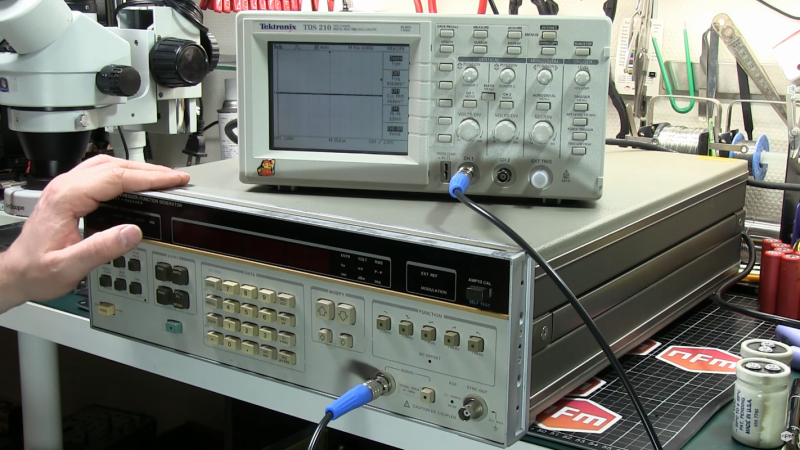
This function generator is an HP3325A and it is several decades old, so some work was needed just to restore it to original working condition. The cooling fan and capacitors all needed to be replaced, as well as a few other odds and ends. From there [NFM] set about adding one of the two optional upgrades available for this device, the high voltage output. This allows the function generator to output 40 volts peak-to-peak at 40 milliamps. While he did have an original version from HP, he actually had a self-made design produced that matches the function of the original.
Even if you don’t have this specific function generator, this guide goes into great details about the functioning of older equipment like this. Most of the parts are replaceable and upgrades aren’t completely out of the question like some modern equipment, and with the right care and maintenance these pieces of equipment could last for decades longer.


I have 2 old HP devices very much like what he is showing, one of which the fan sounds like an old vacuum cleaner.
Question: Should I go through and replace all electrolytics on all boards?
He shows the main cap on the power supply board, but in general should one go through in detail and replace throughout the device?
Anyone have a good link explaining in general terms how to revamp equipment like this? Pozidriv screws were a revelation – I didn’t know about those before watching the video.
Anything that is getting old (80’s and older), I usually replace as I don’t want to be opening the unit again if I can help it and those caps are reaching , or exceeded their rated lifetime.
90’s stuff I make a judgement call depending on the gear and brand of capacitors used. It was smack in the middle of the capacitor plague, so certain caps are swapped out straight away (motherboards, car ECU’s etc).
I’ll often pull one or two caps and test them to check their condition first.
Any caps of that age on the output of a switchmode powersupply is pulled and replaced with equivalent low-ESR, high ripple current rated caps as they will have been stressed more than other caps.
I never bother reforming caps, they are so cheap these days that it is not worth the gamble of potentially damaging other parts of the equipment just to save a couple bucks.
HP-Agilent-Keysight-equipment@groups.io , TekScopes@groups.io and other repair lists on groups.io are the go to places for advice. It varies by make, model and age. Some current gear sold by Keysight was designed 30-40 years ago (e.g. 3458A DMM). It depends on the model and age. Certain instruments have known component problems. Those will generally be replaced if someone is refurbishing instruments.
These things typically weigh 30-50 lbs most of which is steel boxes inside steel boxes. So full recaps are often done if it is necessary to take it that far apart and otherwise not. It can easily be an all day job just to disassemble an instrument to make a repair. The cost of new electrolytics is cheap relative to the labor to get at them.
TheSignalPath YouTube channel is probably a good place to get familiar with the process.
Refurbishing old T&M kit is a complex subject. There are portions of some instruments that if you take it apart you’ve destroyed the instrument.
All of the HP gear of a particular vintage looks similar because they had a common set of cases, knobs, switches and displays to choose from. Same with all the other large OEMs.
Too bad: A missed opportunity to make that high voltage output option an honest full-frequency-range 50 ohm drive instead of the lame reduced-frequency reduced-current output the OEM version featured. The “standard” output could put out 30 dBm into 50 ohms up to 21 MHz. The “high output” option only gives you another 2 dB: 32 dBm, but only up to a measly 1 MHz. A modern equivalent for that output buffer could yield 40-42 dBm at the full 21 MHz range.
Making it a 50ohm output would serve little and cost much.
For example of one concern:
At 40V, the power dissipation at termination would be 40^2/50=32W, quite a significant power to dump into a terminator, and significantly more power than the drive is capable of.
If not using impedance matched loads and lines, there is little point to a 50ohm output.
The HP equipment of this vintage (and earlier) that I have, include a complete bill of materials near the end of the service manual, so any part that’s still on the market can be easily replaced. Eventually they started using a lot of ASICs and kinda stopped producing the BOMs.
Yeah, except for the power supply in my spectrum analyzer, which was outsourced, with no replacements available, no schematic, and no hope. GRRRRRR.
These days, especially whenever the conversation of DIY PCBs comes up people seem to talk like they think there always absolutely must be a soldermask. Check out these HP boards. Solder didn’t flow all over the place nor did the traces turn to dust.