In theory, you really don’t need much to work with electronics. A scope ought to do everything. However, for special purposes, it is handy to have meters, logic analyzers, and other special-purpose instruments. If you work on motion systems like 3D printers and CNC machines, you ought to have a way to look at stepper motors. You don’t? [Zapta] has a great Simple Stepper Motor Analyzer and [Teaching Tech] has a great video (see below) that shows some of the great things it can do.
What can it do? It analyzes the motor in place and can visualize what’s happening during stepping, microstepping, and other operating modes. Connecting the instrument is easy since you just use a four-pin pass-through connector.
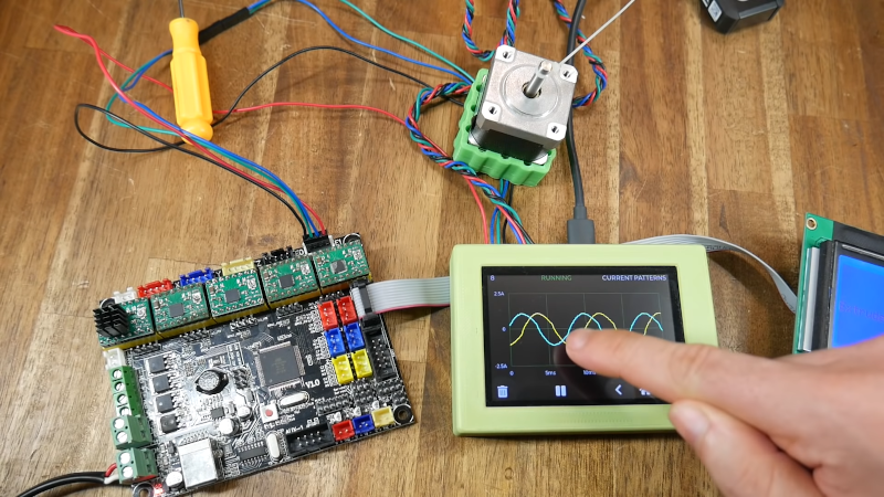
The video has a good explanation of how steppers work including looking at a motor torn down, which is interesting all by itself. Watching the drive waveform for microsteps is a good way to show off the use of the tool.
The tool looks quite useful for setting stepper drive current and the video shows doing that both with a manual adjustment or using G-code, including some thermal images of hot drivers.
Overall, this looks like a useful tool if you run steppers. The CPU driving the machine is a STM32 “black pill” and there’s a TFT display, obviously. A EEPROM and two current sensor chips round out the bill of materials. The FAQ mentions that since device has a USB serial port, so with some changes to the firmware, you could remove the display and just operate from a host computer if you wanted to simplify the project. If you want to learn more about the art of driving steppers, grab a PAL and a 555.


Nice one thanks for post :-)
We need to be alert to developing improved metrology across so many disciplines so we can examine the details at least and discover new opportunities.
This sort of device could be ideal for testing throw away steppers (and potentially servos too) from the mountains of discarded printers, classify/categorise and put them to good use – many I’ve seen are as new and of surprisingly high quality too, I expect given the consumer demand for higher quality prints. Many robotic turnkey offerings could well result :-)
So be alert, the world needs more lerts…
not sure i got the point but this is making me want a simple device i could hook into a circuit in series with my test load that would somehow translate the signal into a form my scope could view (i.e., voltage levels). i mean the obvious choice is a 1ohm resistor, but ideally i’d like both higher sensitivity at the low end of current flow and less voltage drop at the high end.. i guess it’s a hard ask because if there’s no voltage drop then the device would need separate power, and then we start looking a mess of wires (and potentially complicated interactions) real quick..
Use a current sense chip and a battery.
ACS712 worked nicely for me when I needed to monitor a load that was between 1 and 20 amps.
Yeah, or like the old current clamps I’ve once tried that had a precision low resistance resistor and a op-amp that first buffers the signal and then amplifies it.
All powered by a 9v battery and another op-amp acting as “neutral generator” so it effectively had a +4.5volt and -4.5volt power supply.
Micro-stepping is only appropriate for low holding-torque applications where the under-powered phases will not cause an issue. Belt driven 3D printers and laser engravers generally benefit from this approach, but only up to a point where the motors 5% mechanical positioning errors start to feature.
However, few note why this is a problem for most CNC applications where holding a deterministic discrete _repeatable_ position is important. For example, holding-torque in 1/2 step mode is already typically around 70% to 85% of the motors rating in full-step mode. The holding-torque rapidly deteriorates from there with each higher number of simulated indexable micro-stepped positions, and thus precision becomes more probabilistic as mechanical loading starts to skew positions rather than index properly.
In general for small open-loop CNC, a slower speed 0.9’deg nema17 stepper like the JK42HM48-1684 and or a GT2 belt reduction-drive is better (it is my preferred option for 1/2 step mode drivers). Using >=1/4 step mode on something that needs to hold a discrete position under load is usually counterproductive, and thus Trinamic drivers are typically a waste of money in such cases.
I guess it is a personal choice to buy better motors, or gamble on a dodgy driver workaround.
;-)
Great info! Thanks!
nice video, I’d like to see trinamic stepper drivers on the analyzer also, see if there’s any differences detectable on the plots compared to traditional driver modules, especially with advanced trinamic features dynamic current holding etc.
Nice unit indeed, and definitely useful.
I wonder if an additional screen function could be added where, after selecting the motor model/type eg. ‘Nema 14’ it uses that motor’s known values of resistance and inductance combined with its current sensing smarts, and simply gives you a basic ‘GOOD’ on a green background or ‘BAD’ on a red background, with the option to go to a more comprehensive screen.
That way a big pile of motors could be tested in very short order.
Yes indeed, which reminds me I’d like to see various curves eg power/torque re servos, which of course would need a load of sorts. This wouldn’t be that difficult for a range of motors, just the coupling with firmware to handle the feedbacks, heck with a good load switched alternator ah lah impedance matching, with large units mostly, feed power back into the grid, if feasible :D
Also useful: I found that some cheap stepper drivers can be improved by adding an intermediate value resistor across each output, selected based on the DC resistance of the motor (ie 10*)
My reasoning here is that the resistance prevents huge voltage spikes from one or more phases getting unplugged from trashing the driver.
Depending upon the V=Ldi/dt issue is suggest as a backup MOVs or robust zeners on the driver outputs with maybe a smaller resistor to handle the start of back EMF surges. Using just a resistor doesn’t defray the driver damage risk much unless the value is high (and without some capacitance) and you don’t want too high a resistance or much capacity without losing efficiency or affecting driver output feeding suppression caps. Hence why I favour MOVs or sizable zeners with comparatively smaller resistors…
Maybe I’m just missing it, but is there somewhere to buy the PCB?
The OP isn’t selling it, AFAIK, but you can get it made easily enough. Get a couple friends together so you can split the fixed costs, and it’ll even be cheap!
You can get the PCB on Tindie. Look at Electro-General Stores.