Many hardware people around these parts will be familiar with devices used as switches, using at least three-terminals to effect this, an input, an output and a gate. Typical devices that spring to mind are bipolar transistors, triacs and and ye olde triode valve. Can you use a diode to switch a signal even if it has only two terminals? Of course you can, and it’s a tried and trusted technique very common in test equipment and circuits that handle RF signals. (Video, embedded below.)
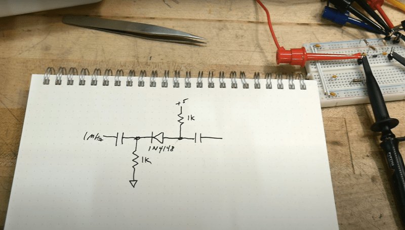
The trick is that diodes block current in one direction but allow it to flow in the other, denoted by the deliberately obvious symbol. So your DC signals can’t swim upstream, but the same isn’t true for AC. Signals can be passed “the wrong way” through a diode by inducing small fluctuations in the current. Put another way, if you bias the diode into conduction, changes in the downstream voltage level result in changes in the current flowing through the diode, and the (smaller) AC signal gets through. But if you take away the bias, by turning off the DC bias voltage source, the diode switches back to non-conducting, blocking the signal. And that makes a diode a DC controlled switch for AC signals.
While [IMSAI Guy] demonstrates this with a signal diode, as he explains, one would typically use a PIN diode, which has an extra intrinsic (undoped) region between the P and the N, allowing the device to fully turn off, reducing leakage significantly.
Of course, we’ve covered diodes many times from different angles, there is always something to learn. Checkout how high voltage diodes are constructed, diodes detecting ionising radiation, and finally this great series about our new favourite two-terminal device.
See, the humble diode can be fun after all!
Thanks [Truth] for the tip!


Ironically, diodes have also been used as variable resistors. For switches, you want them full on or off, but by varying the current into the diode, some level of variable resistance. In some ways thay shows the danger as switches, some arguing against diodes as switches.
PAIA used diodes in their early electronic music projects. Definitely in their first synthesizer, in the VCF and maybe VCA. I’ve also seen diodes used for attenuators in radio equipment.
PIN diodes of course are aimed ditprectly at switching applications.
Then there’s the varactor – using a diode as a variable capacitor.
Diodes can also become fixed capacitors through a process known as transmogrification.
I assume that the transmogrification process involves mains voltage and results in a friode? I’m sure a 1N914 has a characteristic capacitance once that pesky contact has undergone phase change relocation.
Then there’s the Darkness Emitting Arsenide Diode … D.E.A.D.
Actually, No. It appears to be due to vibration.
https://c3.ndc.nasa.gov/dashlink/projects/79/wiki/test_stories_split/
[PDF] – Page 8 to 9.
http://www.rvs.uni-bielefeld.de/publications/DriscollMurphyv19.pdf
There is a video of the presentation which has more detail (and an associated paper too).
Perhaps … Darkness Emitting Aromatic Diode.
A mainstay of “new product” announcements in the April issue of many electronics magazines.
Actually, No. It was due to vibration, with the diode cracking. It occurred on STS-124 with a TMR computer voting incorrectly due to the failure.
I have on occasions make low value (in milliohms) resistors with them. Just run enough current until they break.
The irony being that if you put enough current through them they become useful as current sense shunt.
Which can also be “pumped” by a local oscillator (see parametric amplifier) to make this two-terminal device into a low-noise amplifier. Yay!
IIRC, Before Aliexpress SDRs, varactor tuners were sought out for building low cost Spectrum analyzers.
Before SDR and DSP, accurate frequency synthesis was done with varicap diodes and a Phase Locked Loop. I bit of a mix of analog and quasi digital.
Most people didn’t easily understand a PLL. It’s simply a state transition device. (Finite State Machine).
“Most people didn’t easily understand a PLL.”
Including me (sigh!)
PLL is easy, but making one with dual modulus prescalers requires some more effort.
And temperature sensors, diode logic, hex to binary converters, variable capacitors, ring modulators, non-linear integrator of oscillator stability oh … and … rectifier.
Ring modulators, I think the term has become obsolete, use diodes for switching.
Double Balanced Mixer, as the kids call them now a days.
RF detectors too.
Somewhere in the dim past, tunnel diodes were going to replace transistors. I’ve used them at S band (3 GHz).
According to the lore at Tektronix (where tunnel diodes were used in the trigger circuits of many oscilloscopes, and also in pulse generator circuits with extremely fast rise times), they had to design them out because they’d only made a single manufacturing run for the diodes, just a few wafers.
I found a Sony radio, nice and heavy portable, that even says “Esaki diode” on the front. Another name for tunnel diode.
But yes, they saw limited use, those oscilloscopes are one of the few commercial uses mentioned.
They had potential, but the niche soon lost to other devices.
They made a splash in hobby magazines, I think the novelty of an active two germinal device. Lots of circuits shown, but mostly oscillators. But it was a short period.
In the internet age, more than once I’ve seen people asking where to get tunnel diodes. They found a schematic on the internet, and liked the simplicity. But it was just the schematic, no context. So they had to be told that they were mostly obsolete, only worth buying if you were fixing that scope.
Tektronix had their own fab, and a spiffy complementary bipolar process (25GHz ft IIRC). But they sold their patrimony to f*cking Maxim for a mess of pottage. And when they ran out of old wafers, the TEK4265 ‘scope died.
Dr Ram developed a drop In replacement for the trek u800 hybrid used in the 2465 and similar scopes. Google and you will find it
The problem with tunnel diodes is they only lived like two years in the future ahead of transistors and progress with transistors was too fast (and still hasn’t slowed down).
I would bet that when you were doing S band tunnel diode stuff, transistors were usable at L band and maybe like one product refresh cycle (a couple years) later the next revision used transistors at S band.
A lot of topology problems too. Say you’re doing something MOPA-like, for radar or TV or something, a tunnel diode might replace the MO, but you still need a high power transistor for the PA stage. Transistor technology following its usual trajectory you’d have a great low power MO stage years before someone releases a couple watts transistor for a PA stage.
Once upon a time this was also used in digital circuits, sometimes called transmission or pulse gate. Some applications can be found here: https://archive.org/details/ITT-DiscreteSemiconductorCircuitExamplesOCR (ch. IV)
A few years ago HaD featured a guy who built a clock using an AC source and diode logic, not transistors included. I used diodes and AC signals to implement a frequency divider and a few counters and decoders to drive a 7-segment display.
Diodes can also be used as amplifiers and oscillators. Some are special, like the tunnel diode or DIAC (a PNPN junction diode). But even standard diodes can be used this way in special circuits.
Some power diodes will oscillate at very high frequencies if put in a suitable resonant circuit. You can also build an amplifier with ordinary diodes, with a high-frequency “pump” circuit as it power supply.
Parametric amplifiers use varactors. But yes, averagediodes can be used as varactors.
“Negative Resistance” is the term to search. Bipolar transistors also exhibit this behavior when properly connected, and it can be emulated also with bjt or FET pairs called “Lambda Diode”, sort of a Tunnel diode equivalent built with normal transistors/FETs, very handy to build oscillators, from audio to UHF. Also search for “Gyrator”, which is a circuit showing a similar behavior used in audio circuits (mainly equalizers) to build filters by emulating inductors.
You can also actively amplify capacitance in a similar way. Say having a 50uF capacitor and amplifying it’s effect to 500uF or 5000uF. I surprised that this isn’t often used now with small SMD caps.
I wonder, if I add a diode to the five volt input and using a small length of wire for a phase delay, feed it with the same sinewave as the signal input. Would it be able to output ultra short pulses at the same frequency as the source signal.
I’m not the brightest bulb in the drawer and I don’t fully understand this article, but thank you for it! I will reread and research.
How fast can a diode like this switch? I’ve been working with projects that modulate a NTSC signal for composite TV using the ESP32, but I am also very curious about projects that transmit NTSC video. My idea is to have the ESP32 generate a channel 3 carrier at 56.15MHz on one pin and output an analog, but unmodulated, NTSC composite signal on another pin. An external device, maybe a diode or transistor, would combine those two signals into something that could be broadcast. I believe this would give a better result that projects (such as this one https://www.youtube.com/watch?v=SSiRkpgwVKY) which try to do it all off a single pin. I think it would be interesting to accomplish this with the fewest possible external parts.
PIN diodes are also used inside High Isolation SPDT (Single Pole Double Throw) RF switches going up to multiple gigahertz.
https://www.macom.com/files/live/sites/ma/files/blog/high%20isolation.png
Or a SP8T (Single Pole eight Throw) RF switch https://www.microwavejournal.com/articles/20482-sp8t-50-to-1000-mhz-20-w-switch-design-using-pin-diodes-in-plastic
@Dave Rowntree said: “Is A Diode A Switch?”
PIN diodes [1][2] are routinely used as RF switches [3][4][5].
* References:
1. PIN Diode
https://en.wikipedia.org/wiki/PIN_diode
2. PIN Diodes
https://www.microwaves101.com/encyclopedias/pin-diodes
3. How and Why to Use PIN Diodes for RF Switching
https://www.digikey.com/en/articles/how-and-why-to-use-pin-diodes-for-rf-switching
4. PIN Diode Switches
https://www.microwaves101.com/encyclopedias/pin-diode-switches
5. #118: Basics of PIN diodes and their use in RF switch applications
https://www.youtube.com/watch?v=XpYsCM_Wf50
https://www.youtube.com/watch?v=XpYsCM_Wf50
No mention of Gunn diodes,
their use is not Politically Correct.
B^)
Minor correction: a PIN diode’s intrinsic layer doesn’t improve the shutoff characteristics. It makes them worse.
Diode siwtches take advantage of a diode’s shutdown time, which is a function of the amount of charge stored in the depletion region. When you switch a diode from forward bias to reverse bias, it will conduct current the wrong way until it can sweep all the stored charge out of its depletion region. That’s a common gotcha in making switching voltage converters work without blowing up.
A PIN diode stores extra charge in the intrinsic region, which makes it stay conductive longer in the reverse direction.
When the shutoff time is longer than the period of a high-frequency signal, a PIN diode with enough forward bias acts like a good conductor in both directions. Manufacturers tune the working frequency by controlling the thickness of the intrinsic region.
The diode only stays conductive until it sweeps all the stored charge out of its depletion/intrinsic region, so enough DC reverse bias will make the diode block signals completely.
Diode switches work by flipping the bias between forward and reverse bias.
you never spoke about the amplitude of the AC ,incase its more than the DC pushing the Diode On you will have an issue….