TTL And CMOS Logic ICs: The Building Blocks Of A Revolution

When starting a new electronics project today, one of the first things that we tend to do is pick the integrated circuits that make up the core of the design. This can be anything from a microcontroller and various controller ICs to a sprinkling of MOSFETs, opamps, and possibly some 7400- or 4000-series logic ICs to tie things together. Yet it hasn’t been that long since this level of high integration and miniaturization was firmly in the realm of science-fiction, with even NORBIT modules seeming futuristic.

Starting with the construction of the first point-contact transistor in 1947 and the bipolar junction transistor (BJT) in 1948 at Bell Labs, the electronics world would soon see the beginning of its biggest transformation to that point. Yet due to the interesting geopolitical circumstances of the 20th century, this led to a fascinating situation of parallel development, blatant copying of designs, and one of the most fascinating stories in technology history on both sides of the Iron Curtain. Continue reading “TTL And CMOS Logic ICs: The Building Blocks Of A Revolution”

Secret Ingredient For 3D-Printed Circuit Traces: Electroplating

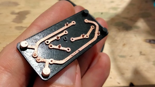
Conductive filament exists, but it takes more than that to 3D print something like a circuit board. The main issue is that traces made from conductive filament are basically resistors; they don’t act like wires. [hobochild]’s interesting way around this problem is to use electroplating to coat 3D-printed traces with metal, therefore creating a kind of 3D-printed circuit board. [hobochild] doesn’t yet have a lot of nitty-gritty detail to share, but his process seems fairly clear. (Update: good news! here’s the project page and GitHub repository with more detail.)

The usual problem with electroplating is that the object to be coated needs to be conductive. [hobochild] addresses this by using two different materials to create his test board. The base layer is printed in regular (non-conductive) plastic, and the board’s extra-thick traces are printed in conductive filament. Electroplating takes care of coating the conductive traces, resulting in a pretty good-looking 3D-printed circuit board whose conductors feature actual metal. [hobochild] used conductive filament from Proto-pasta and the board is a proof-of-concept flashing LED circuit. Soldering might be a challenge given the fact that the underlying material is still plastic, but the dual-material print is an interesting angle that even allows for plated vias and through-holes.

We have seen conductive filament used to successfully print workable electrical connections, but applications are limited due to the nature of the filament. Electroplating, a technology accessible to virtually every hacker’s workbench, continues to be applied to 3D printing in interesting ways and might be a way around these limitations.

Schematic-o-matic

Tricked-Out Breadboard Automatically Draws Schematics Of Whatever You Build

When it comes to electronic design, breadboarding a circuit is the fun part — the creative juices flow, parts come and go, jumpers build into a tangled mess, but it’s all worth it when the circuit finally comes to life. Then comes the “What have I done?” phase, where you’ve got to backtrack through the circuit to document exactly how you built it. If only there was a better way.

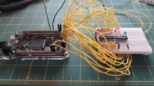
Thanks to [Nick Bild], there is, in the form of the “Schematic-o-matic”, which aims to automate the breadboard documentation process. The trick is using a breadboard where each bus bar is connected to an IO pin on an Arduino Due. A program runs through each point on the breadboard, running a continuity test to see if there’s a jumper connecting them. A Python program then uses the connection list, along with some basic information about where components are plugged into the board, to generate a KiCad schematic.

[Nick] admits the schematics are crude at this point, and that it’s a bit inconvenient to remove some components, like ICs, from the breadboard first to prevent false readings. But this seems like one of those things where getting 80% of the work done automatically and worrying about the rest later is a big win. Plus, we can see a path forward to automatic IC probing, and even measurement of passive components too. But even as it is, it’s a great tool.

Continue reading “Tricked-Out Breadboard Automatically Draws Schematics Of Whatever You Build”