Like a lot of power transmission components, bearings have become far easier to source than they once were. It used to be hard to find exactly what you need, but now quality bearings are just a few clicks away. They’re not always cheap though, especially when you get to the larger sizes, so knowing how to print your own bearings can be a handy skill.
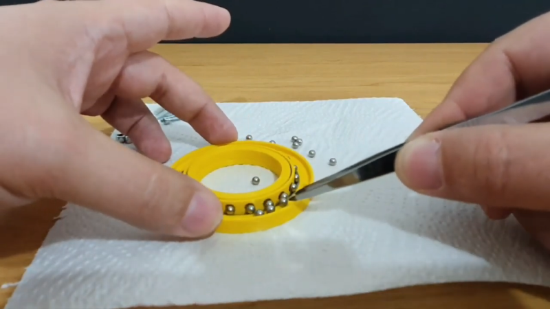
Of course, 3D-printed bearings aren’t going to work in every application, but [Eros Nicolau] has a plan for that. Rather than risk damage from frictional heating by running plastic or metal balls in a plastic race, he uses wire rings as wear surfaces. The first video below shows an early version of the bearing, where a pair of steel wire rings lines the 3D-printed inner and outer races. These worked OK, but suffered from occasional sticky spots and were a bit on the noisy side.
The second video shows version two, which uses the same wire-ring race arrangement but adds a printed ball cage to restrain the balls. This keeps things quieter and eliminates binding, making the bearing run smoother. [Eros] also added a bit of lube to the bearing, in the form of liquid PTFE, better known as Teflon. It certainly seemed to smooth things out. We’d imagine PTFE would be more compatible with most printed plastics than, say, petroleum-based greases, but we’d be keen to see how the bearings hold up in the long term.
Maybe you recall seeing big 3D-printed bearings around here before? You’d be right. And we’ve got you covered if you need to learn more about how bearings work — or lubricants, for that matter.
Thanks to [Nick Dunham] for the tip.


Wonder if he could use the wire rings and bearings to transport power or signal to the rotating layer.
Signals yes, power – not too much, transferring power through bearings changes them into electric discharge machining devices, but they are not designed to last under that usage.
Yes, exactly. Signals would be super noisy and power is a no go. In fact when welding you have to be careful not to put power flow across and moving joint because it is a high resistance point that may cause welding or at least damage to the moving parts. You would be best to incorporate a slip ring concentric with the bearing for express purpose of transferring power and signals. The wiping motion vs a rolling motion makes all the difference because sliding does not have a constant make/break interface like rolling motion does.
Probably possible, but contact might could be flaky, and damage could result if power/signal levels are too high https://www.motioncontroltips.com/what-are-bearing-currents-and-what-causes-them/
If my memory serves me, slip rings for this purpose typically use sliding rather than rolling contacts, although I welcome info to the contrary if anyone has it.
Put some carbon powder in there as a dry conducive lubricant and it’ll probably help.
It’s usually sold to lubricate locks.
I would think its possible. But Depending on the voltages and metal and coatings, and intended life of the part. I would think that there would be a high possibility for damage to the races. Similar to what cavitation does to metal surfaces. A bushing/brush setup would likely be better for such a purpose. Due to increased surface area. Otherwise I believe you experience pitting where the balls contact the inner and outer races.
There’s a nonzero contact resistance but it should be fairly constant if your bearings are worth anything. Of course you’d need at least two.
The usual ways to do this are slip rings and rotary transformers. VCR drums have the latter, one channel per head.
“you’d need at least two”
Nope, https://en.wikipedia.org/wiki/1-Wire
1wire communication still requires ground and power. Power can be harvested from the signal line, but the return line (ground) or path still has to exist.
This gets the vote for “dumbest comment of the year”
The problem with a rolling ball contact is that the actual contact surface of the ball on the race is extremely small but surrounded by an area of very near contact (think arcing across a very small gap). Picture a ball on a piece of glass and you will understand. Over time the whole surface of the ball is subjected to this arc erosion making the ball rougher and rougher finally causing bearing self destruction. Please use a slip ring instead.
I only asked because I had always wanted to try a bearing power distribution for theatrical lighting. Brush ring works, but isn’t without a tradeoff, which is a duty cycle at the power required to get a decent lamp output (at the time I was working with HMI lamps and high voltages). 12 volt quartz lamps could work fine on a brush ring assembly, but anything that was high power would either overheat the mechanism (unless you upped the size, which upped the weight, which upped the motor size and so on…).
Now with LED lamp sources being used in theatrical lighting the power requirement may be low enough to try the bearing power distribution again. And using wireless to control the system for signal would fix it so data doesn’t need to go through the pivot point.
A project for another time.
Hm… Brainstorm-idea: could you do it as a with a transformer? Two spools, wouldn’t have to touch each other, just be close. One on the stationary side, one on the rotating side. Same amount of windings as you don’t want to do any transforming. Just hypothetically?
Unless the light needs to make complete continuous rotation you don’t need a slipping contact. If you are having problems with a slip ring overheating, you problems will be even worse through a ball bearing since the actual contact area is much smaller (a ball touching a hard surface has a theoretical single point of tangent, in the real world there is some squish factor but not much). Sounds like you just need a larger slip ring or more conductive one to get more current carrying capacity. You could also use inductive coupling (think of a 1:1 transformer). You will get no surface wear but you will lose some power to heat in the transformer.
Appreciate the learning opportunity here, but…
I can buy a 6808-2RS for $2.50 (US) (40mm ID, 52mm OD)
True. And even larger ones, for like 5-10 bucks. My whole experimentation with the wire race bearings started 6 years ago, when I needed a 300mm OD, thin cross section, lightweight bearing, for a portable application, and when I found out an aluminium casing one from FRANKE would cost 2000Eur. So I made my own for less than 500Eur. https://youtu.be/6zM2_Yc8O8I
Then, years after, when I bought my 3d printer, my first thought was: what about 3d-printed case, instead of aluminium?
The outer race could be more compact by making the halves snap fit together. The ball cage can be one sided and snap over the balls. Print inner and outer races, shift the inner race to one side to allow balls to be put in then distribute them around and center the inner race. Snap the cage in. Here’s a design I did a while ago for a bearing using 12 steel BBs. https://www.thingiverse.com/thing:1769802
Great insights, Gregg, thank you! And nice design too!
I did prefer the two halves design only for having better control over the preload, as I knew the internal elements are “settling down” with use resulting in an initial increase in slop, which can later be taken out by tightening the periferic screws. As for the roll cage: in normal cases your design is preferred for ease of use. In my case it plays a secondary role: of helping with keeping the balls in place while installing, as the springiness of the wire tends to shoot them out of place while fitting them.
I think there’s a lot of potential for special applications, and also for rerap-oriented projects.
When I found your videos, I was particularly thinking about building linear bearings to run directly on square tube, for a sort of intermediate between the MPCNC (skate bearings on EMT) and PrintNC (profile rails bolted to square tube).
This. Even the most Chineseium of bearings will still be an order of magnitude more accurate and load capable, and cost a couple dollars.
The price isn’t even the point – there’s a lot of “easier” bearings (a simple lubricated tube section, for example) than ball bearings, so when you need a 40mm ball bearing, it’s because you have a specific need for precision and longevity. Really can’t see how a additive polymer production technology would even remotely compete with a precision steel bearing, even of much simpler kind, or even just a lubricated pair of PTFE half-cylinder mantles.
It’s cool you can print a ball bearing. Do you really need a plastic ball bearing?
now, both… think outside the box….
“Think outside the box”
Now that is a phrase misused!
“Thinking outside the box” is exactly what is *not* done by someone building a plastic ball bearing. They have a 3D printer and need a rotational bearing, and instead of thinking what they actually need they just make a very high-effort plastic ball bearing. That’s “in-box thinking”: if all you have is a 3D printer, all problems look like they should be solved by replicating complex objects in polymer.
https://hackaday.com/2017/06/12/big-slew-bearings-can-be-3d-printed/ is a nice example of clever thinking! The materials involved are sensible in the relation of their hardnesses.
Welcome to Hack-a-Day. We talk about hacks, experiments, and other cool stuff. Practicality is optional.
It seems you’re looking for Buy-a-Day.
Nope, I’m looking for hack-a-day, where people hack on things, trying to understand what they’re doing instead of just replicating what they’ve seen before.
Which is exactly what happens here – I see a ball bearing, I replicate it. Never do I stop to think “hey, making a device from polymer whose whole idea depends on the housing being steel-ball compatibly solid, designed for purposes where I need sub-0.2 mm precision, does that make any sense”.
Buy-a-day currently features a list of 3D printers you can buy.
The Hack part is replicating what you have seen before in Plastic. Then make a complete part out of plastic that includes the part integral to the design..
Case in Point, Make a Stepper Planetary gear Box that has bearings Integral to the design that are not a removable piece, and become the actual next part housing. You end up Printing the Bearing Race as part of the ‘Arm’ or Finger’ or ‘Shoulder’ of your finished part.
The Human Knee Joint is not a removable Piece, it part of the Bone it’s attached to..
6318 2Z JEM –
SKF Radial Ball Bearing: 90 mm Bore Dia., 190 mm Outside Dia., 43 mm Wd, Double Shielded – Run over 700
Wouldnt arcing between the bearing and wire races cause pitting in the bearings and races for eventual failure and “crunchy” movement?
That’d depend on the hardness of the steel ring, and how well it distributes the pressure evenly to the surrounding material, and how elastic that material reacts to uneven pressure.
But seeing the whole point of the steel ring is to be harder than the supporting polymer, and comparing this with hard metal inlays in steel bearing which are designed to be flat on the outer side to very evenly distribute pressure…
yeah, I guess it would
WIre race bearings are used for much larger diameters. Instead of making the entire bearing of dense and therefore heavy steel, the housing is often aluminum with a steel wire that has a flat face ground onto it at an angle to the bearing axis and cylindrical rollers run against it. This produces a line-loading rather than the point loading of a sphere on a round wire.
This bearing looks fun, but has too much drag.
Actually bearing with high drag coeficent is useful when you desire something to stop rapidly when red mushroom is pressed (etc. wood cutter with disk blade, chainsaw, drill).
Sorry my english i’m from poland.
I’d rather not have a permanent drag coefficient wasting energy and wearing components when one can be added and removed when required
Recognizing the video shows a proof of concept, the gaps between the ends of the wire rings will make things a bit crunchy.
More to the point, may I recommend the excellent (if highly opinionated) book “Principles of Bearings” by Louis Langhaan, 1922:
https://www.google.com/books/edition/Principles_of_Bearings/Q11AAQAAIAAJ?hl=en&gbpv=1&dq=%22principles+of+bearings%22&printsec=frontcover
Specifically the section titled “Three and Four Point Contact Bearings” which begins on page 62. The first paragraph is:
‘It might be considered difficult to make something actually operative but 100% wrong. It has been accomplished in the design of “three point” and “four point” contact ball bearings, which violate every law of rolling motion and every principle of correct design.’
He then alternates between engineering and hysterics for another four pages.
The key point is that that the ‘points of contact’ are actually ‘regions of contact’ in all real bearings under load. Only regions of contact perpendicular to the ball’s axis of rotation can roll without some amount of sliding. Three point and four point races produce regions of contact at an angle to the axis of rotation, so they have to slide. The result is almost pure grinding motion.
In fact, that’s the basic operating principle of ball grinding and lapping machines.
Two very good points, please let me address them here:
1. “the gaps between the ends of the wire rings will make things a bit crunchy.”
If by crunchy you mean a bit noisier, I believe you’re right. But the noise coming from all the imperfections of such a rudimentary DIY object overpower the noise from the balls stepping over the gaps. Also, this is an overcontrained product (with 4 points of contact) so the load around the gaps is distributed among the other 3 wires, and this makes that “step over” almost inconsequential. Furthermore, since we’re dealing with a hybrid material object (plastic combined with steel), the thermal expansion would put too much stress on the bearing, so having those gaps is actually beneficial while bringing little downsides. Plus, the gaps are staggered so a ball only crosses two gaps twice a rotation
2. If some guys want to theorize any subject to subatom level, like Mr. Langhaan, my hat’s off to them! I’m just a guy having fun in the den exploring intriguing ideas :) BUT I do have a small bit of comment on the grinding action: from my experience, aftwer running the bearings for a while, the balls created their own races in the flesh of the wires, which are now featuring nice uniform channels based on the shape of the bearings. This increases the contact from a point to a line. Both a good thing (stronger contact) and a bad thing (more friction). Not sure how this impacts a specific application as I made these for fun.
Instead of 2 wire circles on the sides, i would have tried 2 rings made of flat strip of metal: one on the inner side, one on the outer. And for the first prototype, i would have put more balls in order to have very little empty spaces left between balls. May be wrong ideas, i don’t know…
Well, the ball has only a point contact so a flat strip is just wasted material, and if you fill the entire raceway with balls, that just makes every single one contact it’s two neighbors, adding heat through friction with each contact point sliding at twice the speed of each ball’s rotation speed.
That’s a really nice and interesting idea, if I follow only half the advice ;)
The current 4 wire design, while beautiful in its symmetry, is a bit overconstraining (3 contact points are the bare minimum, not 4, depending on application, of course).
But only two points of contact I’m afraid are not enough. Think a two legged stool ;)
About more balls: that’s what the intuition tells everybody, but it’s not optimal: you need to reach a balance between too many balls (too much friction) and too few (too flimsy)
Now, given that the bearing cases are made of plastic, it should be a given that it’s not meant for heavy lifting, so less balls are not an issue.