[Curious Scientist] tried building an integrated strain gauge on a PCB, but ran into problems. Mainly, the low resistance of the traces didn’t show enough change under strain to measure easily. Even placing a proper strain gauge on the PCB had limitations. His new design uses a bridge design to make the change in the gauges usefully large. You can see a video of the project below.
Bridging strain gauges isn’t a new idea. However, the novelty of this design is that the PCB has cantilever beams that facilitate the weighing. Standoffs mount a plate to the beams so that weight on the plate cause deformation on the beam that the strain gauges can measure.
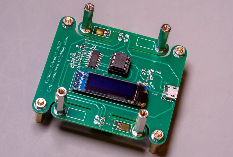
An HX711 module takes care of managing the whole thing. Rounding out the build is a CPU, a battery charger, and an OLED display.
By itself, the output of the device is raw counts, but thanks to the HX711, the output is linear so a simple linear regression can convert the counts to the units you want, such as grams. The resulting line equation is simple enough to implement in the microcontroller, and you can have normal scale units put out on the display.
While the display is nice, there’s something undeniably cool about an analog scale. You might think you don’t need to design a scale, but sometimes you want to weigh something as part of another device. Then it comes in pretty handy.


I suspect that, for various reasons, using epoxy-fiberglass for the flex element would not provide stable calibration over the long term and temperature …
It is not stable, especially when I start up the circuit. After a while it becomes somewhat stable and the drift/creep decreases. However, small disturbances, draft can mess up everything. I printed a small enclosure for the circuit, but it did not help too much.
SMD resistors work well as strain gauges (e.g. https://hackaday.com/2019/01/27/quartet-of-smd-resistors-used-to-sense-z-axis-height/ ), but I’m not sure about their long-term durability and stability.
There’s no documentation on that website, so hard to see what they are actually doing there. Why are only half the strain gauges populated?
And why is the display underneath the object being weighed?
All four strain gauges are soldered in. 2 for tension, 2 for compression, in the same arrangement as you would see them in a typical load cell/Wheatstone-bridge arrangement. The placement of the display is a valid point. However, no one forces you to actually put the display there. You can use 4 wires and put the display anywhere you want.
Hmm. Looking at the mechanics of the thing: Those standoffs are tethered at the top by the clear plate, and constrained to move only vertically: they cannot tilt. That means their attachment face at the PCB cannot tilt. So the segment of the PCB containing the strain gauge is acting more like the rigid middle part of a four-bar linkage: The strain gauges see (nominally) zero deformation! In practice, I’m sure there’s all kinds of uncontrolled bending going on, so they will produce *some* signal.
Sparkfun (and many others) produce useful documentation on how to correctly mount strain gauges, like this: https://cdn.sparkfun.com/assets/learn_tutorials/3/8/2/img0054.png
@17:35 Soldering the square pad looks very strange. Solder iron not hot enough? (Set video to half speed).
@19:30 Using a knife horrible. Use a hotter soldering iron to burn off the lacquer from the wire. This stuff is especially designed to burn of clean by a hot soldering iron.
@20:50 This is still a bad connection. The solder has not wetted the wire properly.
@21:10 Again, R3 not properly soldered. It just formed a solder ball that even gets pushed off the pad.
You have to apply the soldering iron for a longer time. You have to heat the pins properly for the solder to wet the pins. Just applying molten solder is not the same as soldering.
It’s also possible he is just using a very low quality solder. Some of the cheap chinese stuff does not work at all, regardless of skill.
And about the strain gauges…
Even apart from creep, drift with temperature and humidity of the FR4, the way they are mounted is completely wrong.
There is no “clean bend” in the place the strain gauges are mounted, because the metal studs to the transparent top. Tightening of the screws as mentioned @17:50 is also a part. With this setup you also pick up stress caused by temperature differences between the Green FR4 and the transparent top.
(I see now another “Paul” also noticed that).
It’s also beyond me why he put the display nearly in the center, where you can’t see it if you want to weigh anything bigger then a peanut.
I also do not understand the lack of a power switch. How can you forget such a basic thing? Tip: The ubiquitous “transistor tester” has a very nice power off circuit (I measured it at around 100nA “off”, which was one digit on my DMM.
Also making and posting this video without even doing a simple conversion from raw ADC to a weight is yet something else I don’t understand.
The strain gauge not even glued (@25:50) is also enough to make it not work. (as he also suspected).
Gluing of strain gauges is critically important. It is an important part in reducing creep and stability.
Ideal would be to first etch the surfaces (both the strain gauge and the base material) and then use glue especially designed for strain gauges. For DIY, a two part epoxy may be better then cyanoacrylate. (No Mr auto correct, it’s not cyanobacteria, those don’t work for gluing very well).
Should I mentioned the exposed Li-Ion on the back side?
It gets punctured easily if this thing is placed on a not-flat surface.
There are so many things wrong with this video that it it is only good for showing how not to do things. The author is having doubts about some of these things as well. He is clearly not very experienced. There is nothing wrong with that of course, we all have to go though that. Documenting your failures can also be very educational, but presenting this kludge as a valid project is only going to lead to disappointment for other who attempt to reproduce it.
Building a scale with those aluminum “beam type” load cells which cost EUR3 is a much better option. It’s even sold as a kit, and interfacing with HX711 is also quite easy. Use a library or write a handful of lines of code yourself. (There is a code example in the 9 page “datasheet”)
But how will he get input about what he’s doing wrong, if he doesn’t present it to a wide audience, ensuring someone who *does* know what they are doing will tell him?
The soldering iron was hot, but nor powerful enough. The whole PCB was sinking heat and I could not make a perfect solder joint there because I could not heat up the PCB properly. Probably I should not have poured the whole bottom with copper. :) The square connection is the GND, so it was sucking away all the heat from the tip.
Thanks for the tips regarding removing the enamel. I will try it next time for sure.
The connection at 20:50 is not the best, true, but that’s why I checked with a multimeter because I saw that it was not 100% good.
I am not trying to save myself, but I definitely have much better soldering skills that you see in the video. Especially the manual soldering. You had a good guess with the crappy solder. I have a very bad one from AliExpress and I will never buy it again.
The creep is mainly due to the FR4 in my opinion. After the video I kept playing with this circuit to understand it more and I tried many things. I flipped the studs. Then I put the transparent tray on the fixed, non-bending parts and attached the legs to the bending ears. It did not change the behaviour too much. I also released the screws to allow them to move more freely and avoid the error introduced by the too tight screws but it did not help. Even the empty board was producing similar creep so I kind of narrowed down the issue to the PCB. I even glued some strain gauges to another PCB just to see if I can see similar behaviour, and guess what, it was still there. But hey, if I never try, I never know. I am thinking if the behaviour would be different with an aluminium PCB. I almost ordered one when I encountered this issue, but then I saw their price. It would be a too expensive hobby project.
The display is only there for this demo, anyone who wants to use the same board can use wires to place the display anywhere else.
If you check my video carefully at 23:18, you can see that there is a switch that directly cuts the positive wire coming from the battery. The puncture hazard is a real issue, yes. Later on I made an enclosure for this thing (it is published on my IG).
Regarding the chemicals for etching and having fancier glues, I do not have them at home. I don’t work with strain gauges so often so it would not be economically viable to buy those things.
As Jace mentioned, if I don’t post these things, I never know if I am doing it wrong or not. I have this channel mainly because I want to share my hobby with others and not for telling others how (not) to do things. I do stuff, and I share the progress of these things so maybe others don’t have to go through the issues, mistakes…etc. that I have encountered. And also, as now I finally have my video peer reviewed. It is refreshing to read some detailed feedback and it definitely helps my future work, thank you!