One of the great things about the Hackaday community is how quickly you find out what you don’t know. That’s not a bad thing, of course; after all, everyone is here to get smarter, right? So let’s work together to get our heads around this paper (PDF) by [Zerina Kapetanovic], [Miguel Morales], and [Joshua R. Smith] from the University of Washington, which purports to construct a low-throughput RF transmitter from little more than a resistor.
This witchcraft is made possible thanks to Johnson noise, also known as Johnson-Nyquist noise, which is the white noise generated by charge carriers in a conductor. In effect, the movement of electrons in a material thanks to thermal energy produces noise across the spectrum. Reducing interference from Johnson noise is why telescopes often have their sensors cooled to cryogenic temperatures. Rather than trying to eliminate Johnson noise, these experiments use it to build an RF transmitter, and with easily available and relatively cheap equipment.
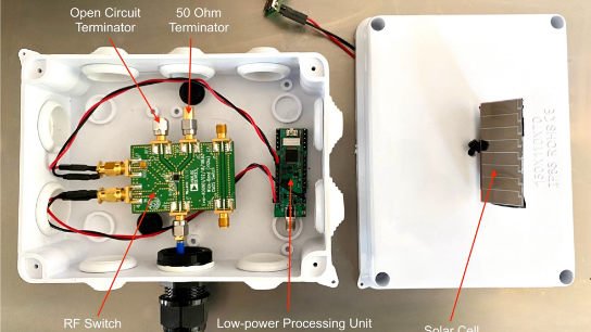
On the transmitter side, we have little more than an antenna connected to the common side of a digital RF switch, an Analog Devices ADG901 eval board. The switch toggles the antenna between a 50-Ohm dummy load or ground; this allows data to be modulated with on-off keying, with the Johnson noise generated by the dummy load representing a logical 1. The antenna is a pyramidal horn antenna made from foil-covered foamboard, offering 13.6 dBi of gain. The receiver is a pair of high-gain LNAs, a bandpass filter, and an SDR dongle with a Raspberry Pi, all attached to an identical antenna.
After running a number of control experiments to make sure they weren’t measuring general RF noise or feedthrough from the RF switch control signal, the authors did several demonstrations of what can be done with this. They were able to show throughput in the 20 bps range at 1.42-GHz, over distances of up to 7 meters, and offered a couple of practical uses, such as a battery-free remote temperature sensor.
It’s important to note that this isn’t using backscatter of ambient RF signals from local radio stations; we’ve seen those before and were suitably impressed with what they can do. This is just relying on thermal noise to generate a carrier, and that’s pretty cool too. We’d love to see someone replicate this — if you do, make sure you drop us a tip so we can write it up.
Thanks to [Reed] for the tip!


Witchery!
People are always talking about the black magic of RF.
https://www.quora.com/Why-is-RF-engineering-considered-black-magic
Here is a video clearly showing RF black magic – 16 minutes and 50 seconds in from the start:
https://youtu.be/eyA2lWQrxwg?t=1011
I nearly died watching this video. Any muggles who saw me laughing to death over a video of RF circuitry would definitely think I was legit crazy 🤣
That is the funniest few minutes of RF circuit “analysis” I’ve ever seen! (And how have I not seen it, as it’s ten years old…)
Fascinating, is that a blown chip at 18:04 or cleverly obfuscating the part number…
The 666 at 18:24 just weird ie 66 MegOhm – what hot place would you get such a beast ?
I’m guessing that resistor is at least a 10% tolerance part, so in reality it is really a 616 hidden in plain sight. ( https://en.wikipedia.org/wiki/Number_of_the_beast )
Why switch the resistor directly at all, just use the heat from one resistor to change the characteristics of the circuit via heating of the other resistor. If it is close to a threshold then the energy required would be low. This can be any resistor so you can select or fabricate for one with as little thermal inertia as possible to maximise the modulation rate. I’m visualising two thin films back to back with an insulator between them.
like the printhead of a receipt printer….
Use old carbon resistors which have much much higher Johnson noise …. The reason film resistors were invented in the first place was to lower the Johnson noise in low level audio and radio front end circuitry. Some of the first noise generators for testing were simply 10 meg carbon resistors that were heated up and amplified.
No, they don’t have higher Johnson noise — no resistor can — because if it did — connecting to a ‘normal’ resistor would transfer (electrical) energy without a temperature difference, thus cooling the carbon R. Carbon resistors DO have higher SHOT noise — but that requires an external current to be flowing and ultimately doesn’t break the laws of thermodynamics.
It’s interesting that the Johnson-Nyquist noise POWER is independent of the value of the resistor (when the load resistor matches that of the source). A 10 megohm resistor generates a lot of voltage compared with a 50 ohm, but the matched power is identical. If there is capacitance in the circuit, things get a little strange as the noise voltage is then independent of the resistance. RF is fun. Microwave and mmwave RF is even more fun.
Interesting but the modulation of the signal and the use of the Analog Devices ADG901 will need more power than can be sourced from Johnson Noise and so the practical suggestion of a battery free temperature sensor does not seem viable unless you are adding an alternative power source which kind of defeats the objective.
I was thinking of a Morse key to replace the ADG901. 20bps is faster than Morse, so even a fast key shouldn’t overload the system.
The issue with that approach is that the contacts of the key and the length of the connecting wire needs to have a consistent surge impedance with no significant discontinuities at microwave frequencies. That might be possible if you used a microwave coaxial relay with an external pushrod to operate the contacts, instead of an electromagnet. That then gives you an entirely passive solution. I think I’d prefer to go for a manually operated waveguide switch with a Morse key attached though. No electronics at all, but you lose the option to use coherent clocked detection modes. Nothing to stop you sending an encoded data stream with your hand key though. The data could contain all the fancy encoding in WSJT-X or EbNaut or Opera modes, although it would be challenging in the extreme to send that by hand. I think I’d stick to using a clockwork metronome for timing and encoding the data in fixed-length blocks with padding if necessary, or simply use many repeats of the same message sent consistently as in moonbounce morse contacts. Definitely possible though.
This reminds me of RF-powered devices, such as RFID ones: connecting or disconnecting a load from the antenna/coil, which gives power surges to the emitter, which can be detected and using information that does not *cost* power to the emitter, but makes the emitter *harvest* power.
Search term: load-shift keying
https://www.icsense.com/inductive-powering-asics/
That is the backscatter method as mentioned in the article.
OK, 7 metres maximum range eh? Sounds like a challenge. I fancy trying a candle-heated resistor and a coaxial relay and a lot more antenna gain. Should be fun. Definitely a good subject for a Machining and Microwaves video
Instead of a resistor, have the candle heat a stack of thermocouples.
Not sure what that would achieve? If there were hot and cold junctions then that could be used to generate some power to run an oscillator, but where’s the fun in that? The core problem of getting the best power out of a warm resistor is about matching to the impedance of the antenna, preferably close to a resistive match, at wavelengths of a few cm. I’d probably try this at 10 or 24 GHz, using some low-sidelobe feedhorns to illuminate some offset parabolic dishes with a -12 dB edge taper to minimise spillover and sidelobes well below -20 dB to minimise thermal noise from the ground/buildings. They used an anechoic chamber. I’d throw much more gain at it and use my best moonbounce LNAs, perhaps even with some Peltier cooling to grab a few more tenths of a dB. The resistor needs to have extremely low self-inductance and self-capacitance, even an 0402 thin-film resistor looks like a tuned circuit at microwave frequencies. I have some annular dummy loads with precision 3.5 mm connectors, rated to 50 GHz at a reasonable S11 so I’d perhaps use one of those and a calibrated short for the other, connecting them over semi-rigid or Sucoform coax to an Agilent 32 GHz-rated coax relay and stick to perhaps 1 – 3 symbols per second and a coding system similar to EbNaut, which can pull out signals from -40dB under noise in 2.4 kHz bandwidth. Might mean 6 hours to send a sentence, but this would be all about fun and silliness, not practicality. There’s far too much practicality in the world already. As my antennas have directivity, the effective noise temperature they can “see” is increased. I can see thermal noise from the moon with my larger antennas, despite it being around 170 K. At only 7 metres, they are scarcely out of the near-field at 1.4 GHz with gainy antennas, so whether it is feasible to get much further once the far-field dominates would be fun to model and investigate practically. I’d prefer to use a waveguide relay and a tapered resistive short for the “hot” source and a full short for the comparison. Barry Chambers is doing some work with modulated thermal sources at 30 THz. He can see the cold moon very easily, and has achieved remarkable distances using a hot black plate as a transmitter. I don’t think we’ll be seeing viable product with passive resistive sources though, because of the need to turn the source on and off using mechanical means. I can use my hand to send thermal noise Morse code signals at 10 to 40 GHz over a few metres just using a microwave power meter and waving my hands about.
“grab a few more tenths of a dB”
HectoBels?
B^)
I read somewhere that an incandescent bulb, as it is a piece of metal suspended in a vacuum, easily reaches fairly high temperatures just by being exposed to external light.
When powered on, the filament gets to a very high temperature and I remember one instance where it emitted so much noise it caused problems with aircraft communication in the area.
That aircraft interference was a fascinating case of an oscillation in the accelerated electron clouds around a festoon filament in a hard vacuum lamp. Rustika lamps were made with a hard vac instead of the usual inert gas sift vacuum. A good analysis of the physics is at https://www.radiomuseum.org/forum/rustika_lightbulb_fm_measurements.html
Most (i.e., all the ones I broke under water) incandescent bulbs do not contain a vacuum. Try it. I used a c-clamp to break the bulbs and an inverted cup filled with water to collect the “not-a-vacuum” that escaped from the bulb.
Idk, if the signal is purely from the resistor, and the modulation is essentially just a SPDT to switch the antenna between R and ground, and the switching rate is so low, why bother with the ADG901 board at all? You could easily drive this by hand, like an old school amateur ‘CW ‘ operator. I.e., antenna, resistor, Morse key – if that couldn’t produce the same result, then I’d guess that nifty eval board was the actual source.
Because the switch needs to be within the transmission line environment at all times.
TL;DR: it’s a cool system. It’s hilariously inefficient, compared to using 1% of the power they use to switch the noise-origin resistor for an oscillator it’s a 1000 times worse in terms of receive power. And here’s the math to show that.
———————–
Hm. For “passive” communications, I’d expect the transmit energy not to come from the origin of the data, which it clearly is here – both as energy needed to drive the switch and heat extracted from the environment through the antenna.
Small problem: Due to the nature of Gaussian noise, you cannot tell the sum of transmitter noise (wanted) and receiver noise (inevitable) from just fluctuation in the receive noise figure *at all*; white Gaussian noise is, literally, in the mathematical sense, the hardest to detect in white Gaussian receiver noise of all possible signals. *Any* other signal, deterministic or stochastic, of the same variance has more mutual information (in a real, noisy receiver) with the received signal.
What that means is that the question “is there transmitted signal or not?” has the highest possible uncertainty when the transmitter is transmitting white Gaussian noise towards a receiver than if the transmitter used literally any other way of forming a transmit signal with the same power.
Of course, it’s plenty cool that the transmitter here simply converts heat to RF and thus will under all realistic circumstances not directly transmit any power that’s coming out of any battery, but as said above: there’s still a switch to switch, and, cough, I think I’ll need someone to show me the actual math that proves your switching energy couldn’t be used for more bit/s when directly fed into the antenna than this noise method in a non-temperature controlled setting (where your receiver can’t know the exact distance nor the exact noise temperature of transmitter and receiver, and where both are subject to change over the day; this might be quite nice on the dark side of a planet with very constant temperature, so that you can calibrate your “off” zero-transmit power and “on” power once, and then can transmit arbitrarily slow, so that your switching energy, divided by the energy extracted from heat as noise power times bit duration, tends toward zero.)
Let us plug in some actual numbers from the paper:
Bandwidth B = 1 MHz
Temperature T = 297 K = room temperature
Impedance R = 50 Ω
Using the well-known J-N noise formula (for matched loads, which is the case here)
P_{TX,on} = 4·k · T · B = 4·(-174 dBm/Hz) · (60 dBHz) = -114 dBm,
i.e., an “on-state” transmit power of 4.1·10⁻¹⁵ W. This happens to be a small amount, but it’s not important to remember that amount – just that we could easily calculate it.
That happens to be the exact noise power the receiver has, inherently: it’s running at the same temperature. But, wait! There’s more. Sadly, a receiver is made out of active components, amplifiers, especially. These have what we call “noise figure”; a very good low-noise receiver still has some 1 to 2 dB worse SNR at its output than at its input. And the paper also measures the noise temperature of the LNA’s (good work!), i.e. the temperature you have to add to the receiver temperature to get the actual receiver noise. That happens to be 40 K, so our effective receiver noise 337 K, and thus, our receiver noise (same formula) is 4.6·10⁻¹⁵.
Notice how that 4.6 is larger than the 4.1? yeah, negative SNR (in decibel), even with **no power loss at all** between the transmitter and the receiver (i.e., “noise free, lossless” direct cable, no antennas) of -0.55 dB = 0.88.
Now, add the transmission loss over a distance that they tested: 3m at 1.42 GHz, with 13.6 dB gain antennas at each end: That makes for 17.83 dB of path loss (assuming good setup). So, we get an SNR at the receiver of -18.38 dB.
Yeah, you *can* work with that. You just need very long integration periods (because that SNR is so small, the channel capacity is *darn close* to 0 bit/s, but not quite). If you integrate for 1/26 of a second (as they do), you get a processing gain of 10⁶/26 = 45.8 dB, so that your SNR becomes -18.4 dB + 45.8 dB = 27.4 dB. OK, with that SNR over the resulting 26-accesses-per-second-channel, the theoretical limit of what you can transmit would be (Shannon’s noisy channel coding theorem):
C = 26 /s · log_2(1+ SNR_linear) bit = 237 bit/s
They achieve 26 bit. That’s more than one tenth, so quite good, actually, for such a simple (read: nice, we like simplicty) system. But, it’s also at a 1% error rate, but I’m willing to take this as a good order of magnitude.
What’s “technically easy” and could use the same power? They state (last page of paper, nearly missed it) that their transmitter uses 0.25 µW; not bad. Had we an oscillator with that power, that had an efficiency of 1% at outputting to an antenna, we’d be transmitting at 2.5 nW = -56 dBm. Adding the same amount of Path loss (-18.4 dB), we receive -74.4 dBm. That is 30 dB more than their system!
So, honestly, yeah. no. You get a 1000 times better reception simply by finding the least efficient naturally occuring oscillator and modulating that instead of switching a noisy resistor.
So, this publication is technologically kinda cool, but it runs afoul of the exact same fundamental mathematical problem as all other “sigma-shift keying” modulation techniques.
Could you please explain what you meant by “You just need very long integration periods (because that SNR is so small, the channel capacity is *darn close* to 0 bit/s, but not quite)”?
How does having a long integration periods increase SNR?
Sure!
So, in “classical” communications, the transmitted signal is correlated with itself. In the extreme case, it’s a constant, for example in OOK: After demodulation your receiver either sees some amplitude A(t) and receiver noise, or just receiver noise:
RX_{on}(t) = A(t) + N(t)
RX_{off}(t) = N(t)
As said, A(t) is a constant, so independent from time t, so A(t) == A.
For RX_{on}, the SNR is
(|RX_{on}|² – E [ |N(t)|² ]) / E [ |N(t)|² ] = |A|² / E[ |N|² ],
with E[…] being the expectation. (Because noise is uncorrelated, the powers of noise and received signal simply add up.)
So, if you now go ahead and integrate for a time interval T up to the current time t,
R(t) = \int_{t-T}^t RX_{on}(u) du
= \int_{t-T}^t (A + N(u)) du
= \int_{t-T}^t A du + \int_{t-T}^t N(u) du
= A·T + \int_{t-T}^t N(u) du
Remember, N(u) is random noise, so when care about the SNR here, we need to work with expectation.
E[ |R(t)|² ] = E[ (A·T + \int_{t-T}^t N(u) du)² ]
= E[ (A·T)² + 2·(A·T · \int_{t-T}^t N(u) du) + (\int_{t-T}^t N(u) du)² ]
expectation being a linear operation
= E[ (A·T)² ] + 2 E[(A·T · \int_{t-T}^t N(u) du)] + E[(\int_{t-T}^t N(u) du)² ]
all 2, A and T being constants, and E being linear
= (A·T)² + 2·A·T·E[\int_{t-T}^t N(u) du)] + E[(\int_{t-T}^t N(u) du)²]
white noise having zero expectation and expected square σ²
= (A·T)² + 0 + T·σ²
= A²·T² + T·σ²
So, in that “integrated” version of your receive signal, you have energies: the energy of a signal of amplitude A, observed for time T, and the integrated noise power for the same interval. Notice how the signal energy grows quadratically with integration time, whereas the noise energy is linear only!
So, for constant signals (or correllated signals where you know the autocorrelation and hence can weigh your integrand such that it becomes constant), the factor between noise energy and signal energy is squared/linear = linear with integration time! neat.
So, small problem with reality (ugh, that guy again): we don’t have a correlated signal we’re receiving in the RX_{on} case, we only have an uncorrelated one. So how do we deal with that?
Instead of looking at the receive signal directly, our receiver takes what it receives and magnitude-squares that: It looks at the signal power, instead of the signal. That is is the only thing we can really do – because a sum of two uncorrelated Gaussian processes is still a uncorrelated Gaussian process, but with the sum variance, and since variance is the *only* parameter of a such a process, we can *only* judge the variance, which is the power.
Now, that converts the transmitted signal and received signals not to be normally distributed, but χ²-distributed with one degree of freedom, with an offset given by the variance of the underlying normal distribution. So, where we do E[ (A·T)² ] above is a bit more complicated, but really just gives the transmitter’s variance times time, squared.
But you’re right – integration of that doesn’t yield the same integration gain. Well spotted!
I am not smart enough to understand how this works, but this seems to be simply switching RF noise on and off. Maybe? That is basically what a spark-gap transmitter did, which splatters noise all over the RF spectrum. While I’m also assuming the transmit power is super low and thus beneath regulations, the spectral purity of this has to be really bad as well.
(I know just enough about ham radio to be dangerously idiotic)
It’s an interesting investigation and I saw another recent article on the same idea, and both imply that something is being had for nothing when in reality the thermal generation of noise is dependent upon the energy we get from the sun. So by extension, the resistor could be made hotter via a magnifying lens, or even a larger Fresnel lens. And by further extension, we could replace the lens with a solar cell and feed that power to a MUCH more effective transistor oscillator. It’s not like transistors are harder to source than resistors, especially when either are compared to a microwave horn.
Reminds me, a bit, of “The Thing”, the Russian bug found in the US Ambassador’s office in Moscow in 1952. It contained no power supply and was thus undetectable by standard bug sweeps. In that case it was powered by RF beamed at it by the Russians, rather than by Johnson noise. Fiendishly clever. https://en.wikipedia.org/wiki/The_Thing_(listening_device)
By an amazing coincidence, I recently made a replica of the Thing for a BBC2 TV science programme with Prof Hannah Fry (available on BBC catch-up – The Secret Genius of Modern Life – Bank Cards). I’ll be making a four-part Youtube video series about the physics, history/disinformation, making of the replicas and my experiences while planting a 1940s-era Russian passive spying bug inside Broadcasting House. Huge fun, plus it was designed by Leon Theremin
Yep, a backscatter communications.
The paper actually compares itself with that – honestly, that would work much better, probably:
By terminating the antenna with 50Ω, it will mostly absorb the energy that you transmit at it (e.g. with a directive antenna from the embassy across the street), but shorted to ground, or left open, i.e. worst-case mismatched, the receiver antenna would become a pretty dumb piece of metal that would scatter the energy it receives. Listen to that reflection, and you know whether the antenna is switched to its matching terminator, or not.
The advantage is that it takes only very little transmit energy to get much more power back from the “unterminated” antenna than that thermal-noisy resistor will produce on its own.
I know it’s not the same as using thermal noise, but this makes me wonder if it would be practical to send Morse using power harvested from a piezo placed under the Morse key…
Sure, not hard to detect the sparks of a piezo-ignited cigarette lighter with a radio. Sure, the energy put into that one spike will be very high compared to how hard you’d want to paddle every keying (notice how the springed mechanism inside such a lighter’s piezo element really forces your thumb to build up quite some tension to be released on a small crystal very quickly!)… but technically it would work. There’s a non-zero effect, and these can be measured. It’d be a very disappointing transmitter, still.
It’s a pretty bad idea; you are actually moving a paddle (even if by a minuscule amount), so just adding a coil and a permanent magnet would produce higher power, or making the crystal integral part of the bearing, so that it get flexed. “putting the crystal where it gets hit” only makes sense if you’re going for high voltage – which you aren’t in a radio transmitter (unless you’re name is Heinrich Hertz, and your transmitting methods are limited to spark gaps. Your ham neighbors would hate you.).
Of course, in the regime of least-power communications, you would abhor from using Morse, that being a very inefficient mode of transporting data (given a specific noise floor, the amount of energy you need to put into a Morse transmitter to achieve a receiver error probability is much higher than with other methods of transporting data); the good thing about Morse is that it’s “human-doable”, not that it’s good by post-1940’s state of the art. We simply have known how to do the same information at the same error rate at lower powers for 80 years now.