So, you now know the basics of approaching PCIe, and perhaps you have a PCIe-related goal in mind. Maybe you want to equip a single-board computer of yours with a bunch of cheap yet powerful PCIe WiFi cards for wardriving, perhaps add a second NVMe SSD to your laptop instead of that Ethernet controller you never use, or maybe, add a full-size GPU to your Raspberry Pi 4 through a nifty adapter. Whatever you want to do – let’s make sure there isn’t an area of PCIe that you aren’t familiar of.
Splitting A PCIe Port
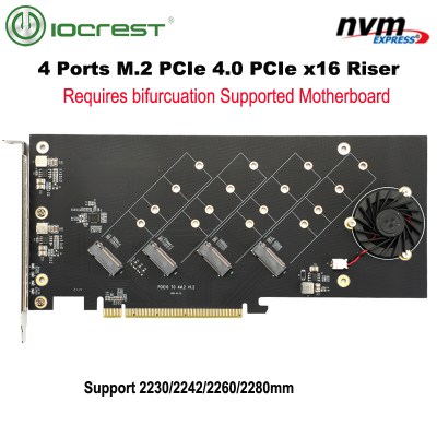 You might have heard the term “bifurcation” if you’ve been around PCIe, especially in mining or PC tinkering communities. This is splitting a PCIe slot into multiple PCIe links, and as you can imagine, it’s quite tasty of a feature for hackers; you don’t need any extra hardware, really, all you need is to add a buffer for REFCLK. See, it’s still needed by every single extra port you get – but you can’t physically just pull the same clock diffpair to all the slots at once, since that will result in stubs and, consequently, signal reflections; a REFCLK buffer chip takes the clock from the host and produces a number of identical copies of the REFCLK signal that you then pull standalone. You might have seen x16 to four NVMe slot cards online – invariably, somewhere in the corner of the card, you can spot the REFCLK buffer chip. In a perfect scenario, this is all you need to get more PCIe out of your PCIe.
In reality, proper bifurcation support is messy. Bifurcation requires support from the host – and this support is quite situational, with only some chipsets being able to do bifurcation, and quite a few motherboards being able to do it but opting to not make it possible software-wise for whatever reason. Even if you’re making your own PCIe host with an FPGA and the sheer flexibility this implies, your FPGA might straight up not support bifurcation for internal reasons. What’s more, you can’t just get sixteen x1 links out of a single x16 slot – usually, the supported combination is four x4 links out of an x16 slot, maybe two x4 links out of an x8-wired x16 slot.
Splitting A PCIe Port Anyway
Now, there’s an alternative, and it’s PCIe switches – these are hefty chips which present a PCIe device interface to your host, and multiple PCIe host interfaces for all your devices; you could compare them to Ethernet switches in terms of how they work, except that lanes of a PCIe switch have either host or device roles and Ethernet switch ports are generally all equal. These switches are sized from a RP2040-style QFN (in case of ASM1182, a 1:2 switch) to the size of a x86 CPU, they will often need external cooling, they also tend to be pricey, and consume a decent amount of power. If you’re looking for bifurcation cards on say, Aliexpress, you will inevitably stumble upon cards with PCIe switches on them.
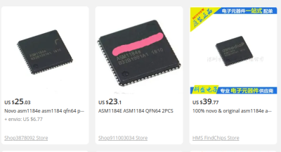
 The benefit is – they don’t require special support from the host, since they look just like any regular PCIe device from a host’s perspective. The drawback – again, they cost a significant amount, and they’re also rarely documented. For instance, I was looking to get some PCIe 1:4 switch chips, and stumbled upon the ASM1184 1:4 controller, which produces four x1 links out of a single x1 link. This was just what I needed, and when googling, I found this chip being used in tons of Chinese PCIe splitter boards of all kinds, desktop motherboards from manufacturers like Gigabyte, with boards even sold in places like Walmart. The ASM118x (1:4 for ASM1184 and 1:2 for ASM1182) chips themselves are easy to find on Aliexpress, too – the main problem is that they lack documentation. Technically, a real-world device schematic is the bare minimum needed, since the chips seem to be meant to work standalone, without external control – I’ve found one for ASM1182, and my friend recently found one for ASM1184. However, things like I2C registers for external control will remain a mystery.
So, even though chips like the ASM1184 is tempting, cheap and is readily available on Aliexpress as both standalone IC and as part of products, debugging might get tricky. Thankfully, there’s one Western manufacturer I know, that will save your day when it comes to PCIe switches – it’s Diodes Incorporated, with their Pericom-acquired PCIe product line; you can openly download full datasheets for their PCIe switches, and there’s a good few on Digikey. You might also stumble upon PCIe switches from Broadcom, but as you might guess, their openness is par for the course for a typical Broadcom product – aka, non-existent.
The Fruits Of Mining
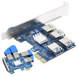
If you’re looking to pull PCIe through a cable and you’re okay with an x1 link, you could do worse than an USB3 cable – in fact, it’s a pretty suitable medium. There’s two high-speed USB3 diffpairs, and given that USB3 is a finicky interface when it comes to integrity requirements, the USB3-intended cabling works well for PCIe. USB3 cables also carry a USB2 pair – and the 100MHz REFCLK pair fits it perfectly; all in all, USB3 cables and PCIe x1 links are a match made in heaven. Mining equipment manufacturers have recognized this, flooding the market with all sorts of accessories that pull PCIe links through USB3 cables and connectors – slot extenders, PCIe switches, NVMe adapters and so on. Ever since mining has become less popular, these accessories are there for the taking, available on the cheap.
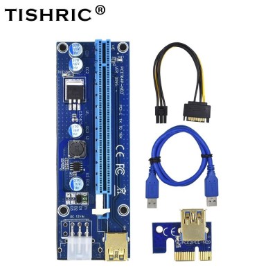
A typical mining riser board consists of an x1 plug board with a USB3 socket that is meant to plug into a mainboard, a x16 slot board with a corresponding USB3 socket, as well as extra power inputs, sometimes, also with some power regulators; the third component is a USB3 cable with USB-A connectors on both ends. For a hacker designing something unconventional with PCIe, reusing these accessories might be tempting – USB3 sockets and cables are easy to find in many varieties, after all.
Indeed, you will likely succeed – if anything can be proof that it’s absolutely viable to peruse PCIe in such a way, it’s that all these mining extenders have, indeed, been working for all the countless miners, in 24/7/365 conditions. However, watch out for a few hiccups. For instance, there’s one minor pinout hiccup that doesn’t occur often – the high-speed TX and RX diffpairs will stay on the USB3 pins, but which PCIe pair goes to which USB3 pair,isn’t quite guaranteed.
 More importantly, though, the kind of signals put on +5V and GND (yes, a separate wire) wires of the USB2 part can differ – and this is known to happen. My friend has built a device with these wires, and the PCIe risers she had, were found to have PEWAKE and PERST, and the design has worked wonders. However, later on, a riser compatibility investigation on a Russian mining forum (translated) has found a few riser and switch boards where the +5V wire carried 3.3V, or even 12V instead – instead of either PERST or PEWAKE that you might expect if you design for the specific riser you own. If you try to design for riser equipment and you rely on either the “in-mainboard x1 plug” or the “x16 slot” boards out of a typical riser extender, you better make double sure that the ones you’re using, do indeed comply to the pinout you have in mind; using a dodgy riser can lead to an explosive situation. Sadly, these risers have almost defined a standard for carrying PCIe over convenient cables – but they’re not quite there.
Also, make sure to avoid the power adapters sometimes included with such miner kits – all those “SATA power to PCIe 6-pin” have a serious mismatch between input and output power; if there’s anything off with those mining boards, it’s the inclusion of these adapters, which can be a genuine fire hazard in practice, if your PCIe card happens to consume a bit more power than the adapter’s cheaply made SATA power connector can handle.
All The Sockets You Can Use
The hacker route of subverting mining accessories for PCIe shenanigan goals isn’t the only one. If you find a tasty chip that connects over PCIe, or you want to extend a PCIe link that you found somewhere through totally legitimate means, go on and design your own PCB! Nowadays, you have the choice between full-size slots for desktop use or M.2 slots for mobile use – and if you’re aiming at older or industrial equipment, mPCIe works too.
For desktop use, there’s an abundance of PCIe sockets to pick from. To plug into such a socket, you need a PCB of 1.6mm thickness – which is, thankfully, the standard PCB thickness that you can get from any fab, and is also the cheapest PCB thickness as a rule, at that! You will want to chamfer the PCB edge that plugs into the PCIe socket – your PCB fab can often do this at a bit of extra cost, but you can also add this chamfer post-factum with a file, or an xacto knife with a spare blade.
As for mobile slots, I’ve talked about M.2 extensively before. The simple M.2 guidelines are – use a 0.8mm PCBs with ENIG for a card, and make sure you have a stencil if you’re adding a M.2 slot to your PCB. Then, pick the keying that you’re comfortable using – A+E for WiFi cards, E sockets for connecting WiFi cards, M-key slots and cards for PCIe up to x4, and B+M cards for PCIe up to x2 and compatibility with both B-key (WWAN) and M-key (SSD) sockets. There’s plenty of M.2 sockets for sale, and templates for both slots and cards, too! For mPCIe, 1mm PCBs will work, and gold (ENIG) plating is, again, a must.
Whether you’re doing a mobile or a desktop PCIe card or socket, the diffpair layout guidelines, the few required signals, and the strong compatibility between link widths and generations stays the same. Whatever you’re designing with PCIe, is not a hard task to accomplish – and thanks to the resillience of PCIe aiding us in our high-speed forays, you are highly likely to achieve your PCIe project goals.


I have also found really good availability of the Diodes Inc pcie switches on Mouser and Farnell/Newark.
Mouser seemed to be the best when I was looking a month or so ago, but that could have just been the luck of the supply chain.
Yep, plenty of P17C9X2G based products for miners on fire sale lately. Sadly x1 2.0 only, but price reflects that. As low as $20 for 1-to-4 x1 2.0 ports, ~$40 for 1-7 one. 500MB/ doesnt sound all that bad.
Is there PCI 3.0/4.0/5.0 splitter available?
Why only 2.0 :(
> You might have heard the term “bifurcation” if you’ve been around PCIe, especially in mining or PC tinkering communities. This is splitting a PCIe slot into multiple PCIe links …
“bifurcation” is to split or device into two. People well versed in the English language may use more than one word to describe splitting something into multiple parts …
bifurcation, trifurcation, quadfurcation, pentfurcation, sexfurcation
(and no “sexfurcation” it is not a naughty word, just one that is rarely ever used these days).
“divide” not “device” – coffee time.
There are two different kinds of people, those who divide people into two groups, and those who don’t.
VM community as well.
Well, considering PCIe lanes are always in powers of 2, *technically* you’re only ever bifurcating, just… doing it possibly more than once.
I guess it could get linguistically complicated. And dumbing down in a technical field, would mean that less of your brainpower will be diverted towards pondering what does that new word that you’ve never seen before in your entire life mean and more trying, to understand what is actually happening with fewer simpler more basic words. And it might not translate easily into other languages could be another reason for simplification.
All I want is to find a way to get the USB signal off of my A+E keyed M.2 slot in my laptop (meant for a WAN card I’ll never want) so I can solder it to the board from a Logitech Nano transceiver. That’ll free up an external USB-A port which I really need as this laptop only has two of them. Thanks to this series, I’m slightly more than half tempted to roll my own.
Thanks!
I misremembered that, it’s a B keyed 3042 sized slot. I put a B+M keyed SSD in it and it’s only got one lane of PCI-E v1.0 active on the PCI-E side. No idea what other signals it has. I hope it has USB because that’s what the WWAN modules use.
There’s probably a “USB 3.0” card that will fit it, complete with blue Type A connector, but it’s really just connecting to the USB 2.0 pins. I had a circa 2008 MPC Transport T2500 (rebadged/recolored Samsung X65) which had an Intel Turbo Memory cache slot. It was actually a standard Mini PCIe slot with the BIOS fixed to not allow other devices to be recognized.
So I got a “USB 3.0” adapter to put in it along with the smallest 128 gig USB 2.0 stick I could find.
What I would have loved to have done was get a Mini PCIe USB 3.0 card for it, tap the power lines to the USB 2.0 in the slot for extra power, and swap out one of the laptops USB 2.0 ports for a USB 3.0 one. It had one on a tiny PCB with wires to the main board so all the hardware would have been easy.
Unfortunately the USB 3.0 cards that would physically and electrically work had bulky connectors, *were stupidly expensive*, and I would’ve had to find a way to mod the BIOS, and nobody was hacking MPC/Samsung BIOS.
It was just a charlie foxtrot all around because for some reason Samsung was still putting CardBus in their laptops in 2008 instead of ExpressCard, despite using PCIe for the internal stuff. I could’ve had quite a bit more use out of that laptop if it had an ExpressCard slot to put USB 3.0 into.
I found a few strange looking cards at aliexpress which looked like they would work, but they were stupid expensive for a passive converter like I needed ($15 for something with zero description of how it’s wired?).
I’m tempted to find a general purpose M.2 breakout board (or maybe have to design one) that just gives access to all the signals and helps you figure out how a slot is wired. I’d need to learn a bit more about M.2, though. It might be nice to put a little uC on it with a USB/ACM connection off to a PC that gives a little text UI telling what signals it sees and letting you toggle signals, etc. It could probably automate some testing, etc.
Watch out, that might be an adapter which breaks out PCIe TX/RX/REFCLK instead, same as the ones I describe being used for mining purposes! Look out for a 5V boost circuit on the PCB, and check the description to be absolutely sure, I’d say.
Thank you! That’s exactly the kind of advice I was hoping for!
@willmore,
Aliexpress sells nvme adapters that break out the usb.
What can i put in M.2 SATA port apart from SSD? I have SSD on M.2 NVME port so i was wondering if i could use M.2 SATA in any other way?
you can put $40 1TB Chinese SSD in there
What is your post purpose?
Where does post info lead?
2023 hardware/software tech info may lead somewhere?
“What’s more, you can’t just get sixteen x1 links out of a single x16 slot”
Okay. But WHY?
Is it a limitation of how the lanes are wired on the motherboard?
A limitation of the BIOS? Can it be modded into BIOS firmware that already supports different configurations like x8/x8, x8/x4/x4, or x4/x4/x4/x4?
Is it a limitation of the CPU?
Considering how fast PCIe 4.0 or 5.0 is, being able to use bifurcation to attach more cheap NVMe drives with fewer lanes is a big deal.
I’d love a Cheap PCIe 3.0 x16 to x2/x2/x2/x2/x2/x2/x2/x2 card.
2GB/s per drive is fine for consumer drives.
There are enterprise NVMe drives that are optimized for an x2 link.
Being able to attach 4x (or 8x) NVMe drives to a PCIe 4.0 x4 (or x8) slot would be a huge boon for a HomeLab or even small business NAS.
There are even people starting to ask for PCIe 5.0 x1 NVMe drives because 3.5-4GB/s is more than a consumer drive will do after the cache fills up anyway.
We may never see 3DXPoint drives again (sad) but being able to run an all-flash NAS with 16+ drives without having to use most of the slots on an EPYC motherboard would help ease the pain.
I’ve been trying to figure out for a while if ‘reverse bifurcation’ could be possible, especially with the trend on newer motherboards to have fewer and fewer PCIe slots and an ever increasing number of m.2 slots.
If it was possible to somehow merge a pair of PCIe x4 m.2 links from the chipset back into an x8 slot, it would make it easier to keep using older, more specialized hardware that really needs those 8 lanes because it only works at PCIe 1.0 or 2.0 speeds.
As far as I can tell, PCIe switch ICs unfortunately don’t do translation between PCIe generations, so no getting full PCIe 2.0 x8 bandwidth for a device from a PCIe 3.0 x4 slot. It’ll negotiate at PCIe 2.0 speeds.
Nando4 figured it out some time ago and his DIY egpu setup (paid program) was able to control width (merging ExpressCard/MPCIE lanes) on older Intel Chipsets (core2 days), sadly I think Intel blocked all of that behind signed firmwares in later chipsets.
I’m pretty sure PCIe switch chips do manage transitions between generations. BW is BW on them. If you have a switch with 4 upstream ports (PCI-E v3) and 8 downstream ports (PCI-E V2), you’ll get full bandwidth on both links. Switch chips deserialize and switch the data internally, they’re not just muxes, so they can convert between speeds.
The only problem being many motherboards have the main x16 slot able to break down into x8 x8 and many modern GPU are x8 4.0 anyway, so you have a place to put your old x8 card. But an X79 H61 mining board has 5 full x8 electrical and is about $40-60 if you really need that sort of thing. It has only one DIMM slot, but mine took a $6 32GB LRDIMM no problem. (They were made to get around a cheesy low hash rate nvidia implemented. It was assumed miners would be using x1 breakouts, and regular users would have at least x8 slots electrically. Cue $5 Xeons with 40 lanes of PCIe from the LGA2011 socket.)
I personally got mine for a video wall project. One GPU to render and nVidia NVS510 in the other slots, up to 20 screens, or 16 screens and 2 NVMe drives.
Great article, Is it possible to send the PCIe from PCB to PCB using normal FFC cable and connector or do i need to design my own impedance controlled FPC flexible PCB? If so how the layout should be in the FPC cable? like (gnd/sig/sig/gnd) or (gnd/sig/gnd/sig/gnd) or (sig1+/gnd/sig1-/sig2+/gnd/sig2-).