Drive along nearly any major road in the United States and it won’t be long before you see evidence of the electrical grid. Whether it’s wooden poles strung along the right of way or a line of transmission towers marching across the countryside in the distance, signs of the grid are never far from view but often go ignored, blending into the infrastructure background and becoming one with the noise of our built environment.
But there’s one part of the electrical grid that, despite being more widely distributed and often relegated to locations off the beaten path, is hard to ignore. It’s the electrical substation, more than 55,000 of which dot the landscape of the US alone. They’re part of a continent-spanning machine that operates as one to move electricity from where it’s produced to where it’s consumed, all within the same instant of time. These monuments of galvanized steel are filled with strange, humming equipment of inscrutable purpose, seemingly operating without direct human intervention. But if you look carefully, there’s a lot of fascinating engineering going on behind those chain-link fences with the forbidding signage, and the arrangement of equipment within them tells an interesting story about how the electrical grid works, and what the consequences are when it doesn’t.
From The Ground Up
The most basic function of a substation is to transform voltages, either stepping up the voltage from the point of production for efficient transmission over long distances, or stepping voltages down from transmission systems to feed regional or local distribution systems. That makes substations conceptually simple, but as is always the case in engineering, the details are where things get interesting.
While the equipment mounted above the ground is the easiest part of a substation to observe, what you don’t see is arguably far more important, at least in terms of safety. A note to frame the discussion: we’ll be concentrating on open-air substations, rather than substations that are inside a structure, which are an important and interesting part of the grid, but harder to observe casually.
Substations must have an extensive grounding system, both for worker safety and to provide the needed neutral reference. Most substations use a grid of thick copper conductors buried just below the surface, tied together at regular intervals to ground rods extending 25 feet (7 meters) or more into the soil below. Horizontal and vertical conductors are tied together with exothermically welded connections or cold-forged fittings to form low-impedance electrical connections between every element of the grid. The grounding grid spreads out under the entire area of the substation, and everything is bonded into the ground system by heavy, low-impedance braided straps.
Over the grounding grid is a layer of crushed rock about 6 inches (15 cm) thick. The gravel serves several functions, including aiding water drainage and inhibiting weed growth. But the main function is worker safety in the event of a ground fault, which could cause a lethal voltage difference between the above-ground equipment and the earth. The high resistivity of the gravel (3,000 to 5,000 ohm-meters) compared to the soil makes it less likely that a worker will conduct these voltages through their body. Also, gravel reduces the possibility of lethal voltages between one foot and the other while walking, or step voltages.
Every substation also has a fence or physical barrier of some sort. Most are imposing structures of heavy-duty chain-link topped with razor wire, but in some residential areas, a more decorative option might be used to appease the neighbors. Some substations also have sound barriers, to reduce the incessant 60 Hz hum of the equipment within that could annoy nearby residents. The characteristic hum has also been known to attract bears, who apparently think they’ve found the world’s largest beehive. A sturdy barrier is critical to avoiding unpleasant consequences for the bear, or for those with a greedy eye on the multiple tons of copper most substations contain.
Rule of Threes
Of the above-ground equipment in the substation, the most visually striking structures are those that support and terminate the wires coming into and leaving the yard. These are loosely referred to as “high side” and “low side” lines based on the voltages they carry. A substation might have a 345 kV high side to receive power from a transmission line and several 25 kV lines on the low side feeding different local distribution lines. Some substations will also have multiple high-side feeds from different transmission lines, or may have multiple low-side inputs from wind or solar plants that the substation will combine into one or more high-side transmission lines.
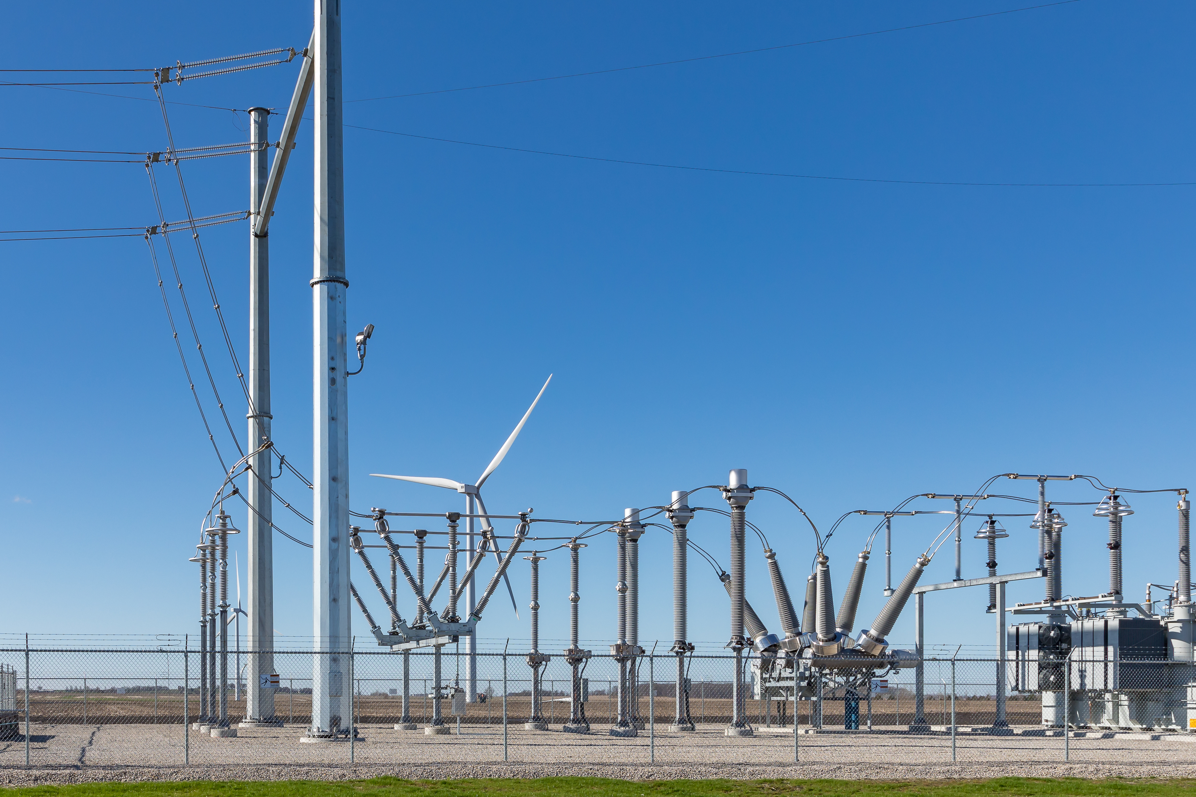
Something that stands out about most substations is that there seem to be three copies of each piece of equipment. Each set of high-side lines comes into the substation in a set of three, there are often three transformers (or one transformer with three input bushings and three output bushings), and all of the gear between the input and the output seems to be in triplicate. This is thanks to the three-phase electrical system in North America. Electrical transmission and distribution systems are all three-phase power, and while residential customers rarely enjoy such service to the home, commercial and industrial installations almost universally have it.
While the high-side and low-side lines entering and leaving the substation are generally — but not always — overhead wires, inside the substation, most of the components are connected by a series of overhead busbars. Busbars are simply pieces of metal pipe, often galvanized steel or aluminum and usually in groups of three, which are attached to equipment bushings either directly or via jumper wires. Busbars have the advantage of not sagging or swaying in the wind, but do have a few disadvantages, too. When busbars get hot they expand, and since they’re rigid and supported firmly on each end they’ll either buckle or break their supports. That means busbars have to be provided with expansion joints.
![A 3-phase SF6 circuit breaker. The bushings on top bring power in and out, while the breaker contacts are in the horizontal cylinders, which are filled with sulfur hexafluoride gas. Source: Adobestock, by [sergbob]](https://i0.wp.com/hackaday.com/wp-content/uploads/2024/08/breakers.jpeg?ssl=1 "Electric power substation")


Another potential failure mode for busbars is ice damage, which I witnessed back in the 1980s. During a late winter thaw, meltwater had accumulated in a busbar at a substation near my home. When the temperature dropped precipitously that night, the freezing water exerted enough pressure to burst the busbar, which caused a fault on one of the phases bad enough to trip the entire substation. This knocked out power to the entire town and resulted in the local utility asking for help from my volunteer fire company.
The substation techs used the enormous generator on our truck to power a welder so they could make an impromptu repair to the busbar and restore power. It was a long, bitterly cold night, but I got to walk around inside a substation and check things out. It was pretty cool.
Plenty of Protection
That brings up the topic of control and protection. The vast majority of the equipment inside a substation is devoted to circuit protection, in the form of circuit breakers, fuses, reactors, and capacitors, followed by the equipment needed to control and monitor the circuits. Lightning protection is also vital, since a nearby strike can induce currents that can permanently damage equipment. Protection starts at the top with static lines on the highest part of transmission towers that are designed to catch discharges and run them directly to ground. Static lines are now often hybrid cables called OPGW, or optical ground wire, which has one or more optical fiber pairs at its core. These fibers are used for control and communications between substations; some utilities even lease the extra pairs out to communications providers.
Circuit breakers play a last-ditch role in substation protection, and are capable of disconnecting the entire substation in a catastrophic fault. They’re pretty easy to spot thanks to their angled bushings, usually two per breaker with one breaker per phase, although some breakers have three bushings each. The breakers are just super-sized versions of those in your home panel and work in a similar way, albeit tripping at a much higher current — often 5,000 amps or more. They also have to switch very rapidly, a tough job when there’s enough voltage to keep an arc going between the contacts even when they’re fully separated. So circuit breakers are often filled with a dielectric gas such as sulfur hexafluoride (SF6), a liquid dielectric like mineral oil, or even evacuated completely. Air blast breakers which literally blow the arc out are also used.


Another interesting bit of control equipment in the yard is the voltage regulators, which are essentially autotransformers that can adjust the voltage on a phase within a small percentage range. These are easily recognizable as a set of three tall cylinders, each bearing a large dial on the top. The dial shows how much voltage is being boosted or bucked, and is usually angled downward for easier reading from the ground. Substation switchyards also often contain banks of high-voltage capacitors, which adjust the power factor and compensate for noise on the line. Capacitor banks are usually located on the distribution side of a substation along with neutral grounding reactors, which are large, cylindrical inductors that are connected in series between the neutral of a transformer and ground and limit current if there’s a phase-to-ground fault.
Sprinkled liberally around the substation are instrumentation transformers whose entire job is to monitor the flow of current into and out of almost every piece of equipment. Current transformers, or CTs, are just permanently installed, beefed-up versions of the clamp meter you might use for measuring current in an electrical panel and work pretty much the same way, with current in the conductor under measurement inducing a proportional current in a toroidal coil. Voltages are measured with voltage transformers (VTs), the most common of which is the capacitive voltage transformer, or CVT. These use high-voltage capacitors as a voltage divider and a transformer to isolate and further step down the voltage to a reasonable instrumentation range. The outputs of instrumentation transformers are generally piped into a supervisory control and data acquisition (SCADA) system that remotely monitors and controls everything in the substation, right down to alarm contacts on the fence gates.
The Diva Treatment
Since the primary job of the substation is changing one voltage to another, the main power transformers are the centerpiece of the switchyard. In a lot of ways, transformers are the divas of the substation — they’re expensive to procure, require a lot of maintenance, and the show won’t go on until they’re happy. The transformers are easy to spot, since they’re generally the largest pieces of equipment in the yard. In keeping with the rule of threes, there are usually three identical units, one for each phase, although some transformers have windings for all three phases in a single massive enclosure.
Almost all substation transformers are filled with mineral oil, which acts as a liquid dielectric and helps cool the transformer thanks to giant radiators and fans for forced-air cooling. A large transformer can hold thousands of gallons of oil, an environmental disaster waiting to happen if there should be a leak, which given some recent rural substation attacks is not unthinkable. That makes secondary containment a necessity, with deep pits dug around the transformer foundation pads. The pits are lined with thick plastic sheets and backfilled with gravel. They’re designed to contain the entire volume of oil if necessary, and sump pumps with oil separators keep rainwater from accumulating in the pit.
In keeping with the diva treatment, transformers require constant monitoring to ensure they operate at their peak. Aside from the instrumentation used to measure their electrical status, transformers need to have their oil checked regularly for chemical changes that could indicate internal problems like arcing and overheating. This can either be performed by a technician visiting the substation and taking samples of the oil, or through online dissolved gas analysis (DGA), which uses a compact gas chromatograph to automatically sample the oil and measure the amount of acetylene, ethylene, and methane dissolved within it. Continuous measurements are collected via SCADA and provide a much more accurate picture of transformer health than monthly or quarterly sampling.
And finally, to push the diva metaphor even further, transformers are often provided with pressure-relief devices to protect the system in the event of an explosion within the transformer enclosure. PRDs can be as simple as a burst disc that shatters under increased pressure, but are more commonly sensors that detect and characterize the pressure wave from an internal explosion as it propagates through the oil. If the pressure wave looks like a catastrophic internal failure has occurred, the SCADA system will disconnect the transformer, in an attempt to save it from irreparable damage.


What we take for granted every day. Thanks for this. It is interesting to understand what’s in the ubiquitous stations.
I’m loving the Field Guide series!
Really really neat reading! I’ve always wondering about substations. This is a great overview.
@Dan Maloney said: “PLENTY OF PROTECTION”.
Great overview of an often visible but rather obscure infrastructure subject, the electric substation. It probably deserves its own article, but I would like to see a deep dive on how (or if) the electric grid protects us from electromagnetic pulse (EMP), either natural or human-made – and if we are not protected from EMP, that is an existential problem! Why are we not protected, and who is responsible?
Other common transformer protective devices are breathers with silicon gel canisters to prevent the transformer drawing in moisture from the outside air as the oil heats and cools during operation. Alternative the transformer air space can be sealed and nitrogen filled which in addition prevents contact between the transformer oil and oxygen in air.
Rather than just detecting a pressure build up from an explosion in a transformer, if a minor fault is occurring, such as partial insulation breakdown or a hot joint, the heat produced by these faults creates gas bubbles in the oil. The gas bubbles get collected in a device called the Buchholz relay and eventually this trips signalling a problem.
Thanks, that’s some interesting information.
Will also mention the risk of explosion is severe, should the oil in the transformer overheat and atomize. This happened at the Fordsburg substation in Johannesburg, South Africa some 30-40 years ago, and absolutely destroyed the entire 275kV-88kV substation, as well as damaging substantial portions of the area around it.
I googled for some pictures, which I know were online at one stage, but sadly bitrot seems to have claimed them.
Great article Dan, very informative. The only improvement I can think of is some labeled pictures or drawings of the components you mentioned. (for example, the oil conservator…where is it in the picture?)
I’ll second what others have said, the Field Guide series are great.
-Greg
Replying to my own post; I just noticed that some of the images offer additional ID notes on mouseover.
“A sturdy barrier is critical to avoiding unpleasant consequences for the bear, or for those with a greedy eye on the multiple tons of copper most substations contain.”
Imagine that doesn’t end well for the copper thief. Bigger threat is people with guns.
Unless accompanied by an trained and authorized power company worker, one should not enter a substation. Ever see the hotdog-plugged-into-an-outlet demonstrated? That’s you, touching the wrong thing, if it doesn’t simply explode and/or vaporize the tissues in the current path.
As part of my internship at the local power company, our safety videos had a high cringe factor. Live video of breakers coming back out (at high speed) of the cabinet due to shorts during racking, phase-to-ground arcs on the back side of a breaker (limited by the upstream breaker — which just thought it was a load), etc. Lots of “this is what you might look like after your arms have been cauterized off” stuff.
Electricity will kill ya, kids.
That is really well explained. I have been in this game for 38 plus years, and am impressed how comprehensive the description was.
i enjoyed watching them build a substation by my house…just like the article says, there was a lot of surface prep. they came along and flattened and graveled the land very meticulously, and then a month later they came through and dug a bunch of pits and trenches. seems like there were half a dozen waves of that, each digging into what they had just done. of course, it makes sense if you realize all the things they’re doing. took the better part of a decade if you count the time it took to run 2 miles of new transmission line to it.
one of the cool features is the local high voltage lines have a 3-try system on the breaker. the tree lands on the line bridging two of the phases, there is a huge arc and boom, and something somehow detects that arc and turns it off. but it auto-resets after a few seconds, and tries again. nope, tree still there, new arc, new cut-off. after the third arc, it turns off for good. makes a neat cadence – boom silence boom silence boom silence.
upside is, if it’s a small thing that falls off or gets vaporized by the arc, then it automatically restores service without intervention. downside is, each time it sends an arc through to see if it’s cleared yet, it is exploding bits of flaming tree (or squirrel) down onto the grass below. luckily the event is hard to miss so the fire truck comes next :)
Very interesting! thanx!
And they invented most of this stuff 100 years ago. Electronic controls are young compared to the transformer and relay controlled grid.
I marveled at seeing a breaker using a linear motor in series with the load that turned a brass disk on a clock spring. If the average load current was too high, the disk rotated until a peg tripped a contactor. This wasn’t a one off contraption, it was in common use at substations and factories. Those guys were geniuses.