[JanTec Engineering] was fascinated by the idea of using a 3D printer’s hot end to inject voids and channels in the infill with molten plastic, leading to stronger prints without the need to insert hardware or anything else. Inspiration came from two similar ideas: z-pinning which creates hollow vertical channels that act as reinforcements when filled with molten plastic by the hot end, and VoxelFill (patented by AIM3D) which does the same, but with cavities that are not uniform for better strength in different directions. Craving details? You can read the paper on z-pinning, and watch VoxelFill in (simulated) action or browse the VoxelFill patent.
With a prominent disclaimer that his independent experiments are not a copy of VoxelFill nor are they performing or implying patent infringement, [JanTec] goes on to use a lot of custom G-code (and suffers many messy failures) to perform some experiments and share what he learned.
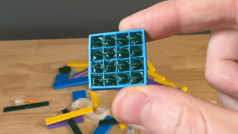
One big finding is that one can’t simply have an empty cylinder inside the print and expect to fill it all up in one go. Molten plastic begins to cool immediately after leaving a 3D printer’s nozzle, and won’t make it very far down a deep hole before it cools and hardens. One needs to fill a cavity periodically rather than all in one go. And it’s better to fill it from the bottom-up rather than from the top-down.
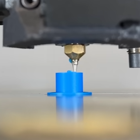
He got better performance by modifying his 3D printer’s hot end with an airbrush nozzle, which gave about 4 mm of extra length to work with. This extra long nozzle could reach down further into cavities, and fill them from the bottom-up for better results. Performing the infill injection at higher temperatures helped fill the cavities more fully, as well.
Another thing learned is that dumping a lot of molten plastic into a 3D print risks deforming the print because the injected infill brings a lot of heat with it. This can be mitigated by printing the object with more perimeters and a denser infill so that there’s more mass to deal with the added heat, but it’s still a bit of a trouble point.
[JanTec] put his testing hardware to use and found that parts with infill injection were noticeably more impact resistant than without. But when it came to stiffness, an infill injected part resisted bending only a little better than a part without, probably because the test part is very short and the filled cavities can’t really shine in that configuration.
These are just preliminary results, but got him thinking there are maybe there are possibilities with injecting materials other than the one being used to print the object itself. Would a part resist bending more if it were infill injected with carbon-fibre filament? We hope he does some follow-up experiments; we’d love to see the results.


What about concrete infill?
This, or some sort of resin etc.
Simply a liquid that’s poured in from a separate nozzle. Should be pretty simple to implement, just a tube and valve strapped to the side of existing extruder. Pay attention to setting times and maybe make a waste catchpot to keep the tube unblocked during longer prints.
Would mean there’s theoretically no limit to the depth of hole, or even the shape if air pockets are taken care of.
You could add a vibration motor to the bed to eliminate voids.
You could also just vibrate the bed with the stepper motors
Timing belts have left the chat
There’s an open source mini lathe that is 3d printed and filled with concrete
I am having trouble finding info about that lathe. Any chance you have a link you cpild share?
https://www.youtube.com/watch?v=6Js8erWbsDQ
Maybe this?
https://youtu.be/6Js8erWbsDQ?si=-Sila5HUVNcti7_Q
The photo makes it look like an array of lights
i’m amazed this works at all. the material isn’t really flow-y enough to fill a volume. when i actually want to strengthen a void, i fill it with a bolt or a dowel rod instead. these hacks to get X% more strength out of printed plastic seem to be of limited utility. there’s a very narrow range of requirements where the load is enough that plain reasonable-thickness reasonable-infill plastic won’t do it but hacked plastic will.
So, this could be part of the “make it strong” profile on a slicer”, or you could make it stronger by….
Having a stock of pins/dowels in the right size, remembering to use them, being capable of using the slicer or other CAD to put in a properly dimensioned hole, and installing it post print without cracking the part.
I wonder which one has better scaling a user friendliness?
the dowel rods have better scaling and user friendliness because everyone’s already doing that and this article is just a one-off hack :)
Rather than dowels another approach would be to use standard issue linoleum wedges and a bicycle seat. Undetectable.
The Hackaday summary doesn’t really delve into it, but these aren’t about increasing strength as such, they’re about making parts more isotropic. FDM prints typically suffer a lot from having a weak axis due to being composed of a series of generally pretty strong layers that are relatively weakly bound together – all of these strategies are aimed at automatically creating bridges between those layers (z pinning in particular is literally about pinning the layers together) to mitigate that. There are ways to make parts much stronger than this of course but these strategies could be incorporated into slicers since they just use the extruder that’s already laying down the part, albeit potentially with a modified hot end in this case.
but that’s exactly what i’m saying. i guess i’m countering my own wisdom here, because i do definitely think about the orientation of the part when i’m designing it, to try to avoid hanging a load on layer adhesion. but the fact of the matter is, the layer interfaces are pretty strong. it’s not like it’s 10x as strong in one orientation as another. maybe ABS users have a different experience but with PLA and PETG my feeling is that strength in the different orientations is within +/-20%.
anecdotally, i often break my preference and put a (small) load supported only by layer adhesion and i never have a problem with it. if it’s at all a big load though then i need bolts no matter which orientation it is.
a real eye opener for me was … for a decade, i printed always in PLA. and i made a couple brackets to hold a 1/2″ copper pipe as a curtain rod. it was supported entirely by layer adhesion, with a cross section of about a square centimeter. it weighed about a half pound, and it was on my front door so it saw a lot of abuse. it lasted fine for 2 years and then failed to brittleness, like everything else i printed with PLA. 2 years is a relatively early failure, i get up to 10 years if there’s no static load, minimal dynamic load, and no sunlight or water.
in the post mortem, it did delaminate, but not at the place with the smallest area! it was built as a base and an arm, and the small amount of delamination that occurred was 3 layers deep within the base, and larger than the root of the arm! the layer adhesion at the root of the arm was enough to pull up those 3 layers and then tear them before it started delaminating anything. and the layer adhesion within the base was enough to tear the layers in the middle of them without delaminating them at the ends.
so ymmv but delamination is just something that happens when the part fails because you engineered it for a bigger load than the plastic was capable of supporting. if you’re within reasonable margins then the orientation doesn’t matter, and if you exceed those margins then orientation also doesn’t matter, it will fail either way
haha while writing this up i realized how i should have redesigned it for longer screws. instead i just added some filleting and printed it again…printing it over in PETG is on my todo list
There are signmaking 3d printers that have a separate nozzle for UV curable resin and a heated glass bed lined with UV lamps – similar to https://www.youtube.com/watch?v=gGCD03feE9E .
That seems like the best use case for that process (if you are into eye-watering multicolored signs).
I was scrolling looking for this. All the strength of uv resin and not nearly as much heat.
I do this with a replacement part I need to periodically reprint for a cigarette rolling machine. The reinforced section is actually a shear pin, simply 3d printed, even solid, sheared too easily. I use a 3D pen to fill it, and I have the tube shell backed up with aluminum so the shape is maintained. The pin is driven by a geneva gear, so when sheared off it just travels around and the machine gets no more stress.
The original has a bearing here and when it fails it pulls out parts from below it, so it can damage the machine pretty bad, especially if somebody keeps trying the button. They do not sell this part either, you need to send your machine back for repair. I’m probably on the tenth replacement, and it’s become a consumable, like it should have been.
Suddenly I’m thinking “why didn’t I think of that?”
Also I’m thinking “ok, leave some very small openings at the top of the voids and inject them with a syringe full of JB Weld (60% super fine powdered stainless steel in epoxy)”. It makes me wonder if I would be reinforcing with JB Weld or if I would just be 3D printing molds to make parts from JB Weld. Maybe when the stuff cures I could wash away the PLA with acetone and have an arbitrarily-shaped JB Weld part. Maybe that would work with any “cold cast” metal powder – brass, gold, uranium… probably not the latter.
I’m sure the goal here was to do it all in one automated pass, so clearly it’s a different objective and I salute the accomplishment. I’m just thinking about what I can do with a box of needles in my toolbox and no West Virginia Party Powder.
Modifier mesh -> cylinder -> infill -> 100%
FTFY.
I would imagine the print time would be quicker his way but yeh who knew solid plastic is stronger than hollow plastic
Ideally, you’d want a spiral filling mode here (a kind of vase mode). But this doesn’t actually solve the isotropy issue since even with this setting, the printer will just stop filling the cylinder for each layer (to continue printing everything else on that layer). However, the idea in this article is, IMHO, stupid. There’s no additional strength to be gained from more than 2 layers (maybe 3). Worse, because it’s injecting plastic in a very lightweight container, it makes the whole part weaker: the infill wall aren’t made to support injection pressure and the wall layer will simply split in that case.
When the printer goes over an existing layer of plastic, there’s a remelting action that gives strength to the bounding with the previous layer and the new layer. Here, since the injected plastic (which is hot, but clearly cools quickly), will contact a very cold layer of plastic (the infill bottom), no such remelting will happen, you’re just layering 2 different material here. You’d get the same results, IMHO, to simply embedding plastic nails in your part, like his tests on impact resistance have shown.
Moreover, the hot mess of the injected plastic here has a strong thermal gradient, so its exterior skin cools even faster when it contacts the infill layer while the interior content stays molten. So it won’t really fuse with the infill’s container, unless pressure is increased which, in turns breaks infill’s own interlayer adherence.
It would be better, IMHO, to simply fill only one or 2 layers of plastic instead, so that the plastic that’s injected is hot enough to actually remelt with the cold “previous” layer plastic. Typically, you’d want to inject the equivalent to 2 (or 3) lines into a 2 layer deep hole while still following the infill’s wall so that the plastic hot section is always in contact to some plastic instead of hoping for the best here. You’ll fill with a spiral going inward (from the infill’s wall container to the center of the cylinder) so that the exterior skin is always in contact to a hot or cold region.
I don’t have an impact resistance test bench so I can’t prove this, but that seems intuitive to me.
I still want to see someone testing leaving a hole and trying to directly fill gyroid infill. IIRC one of the features of gyroid infill is the entire inner void is connected so should be possible to fill.
Also I think we need to look at non-plastic and cheap alternative fillers. Something as simple as sawdust and wood glue or paper pulp and a glue or even coffee grounds (I remember some people trying them as filament filler).
Check out Peter Brown on youtube – @peterbrownwastaken – similar idea, he printed gyroid infill and filled it with resin and then turned it on a lathe.
Seems like an improvement now to have a multiple tool-head 3D printer where you could have an alternative nozzle just for the infill.
Just filling the one or two cells closest to the perimeters would probably significantly improve strength without using too much material…
The infill could be a different type of plastic – for example, two part epoxy, or uv curable resin, etc