If you want to dyno test your tuner car, you can probably find a couple of good facilities in any nearby major city. If you want to do similar testing at a smaller scale, though, you might find it’s easier to build your own rig, like [Lou] did.
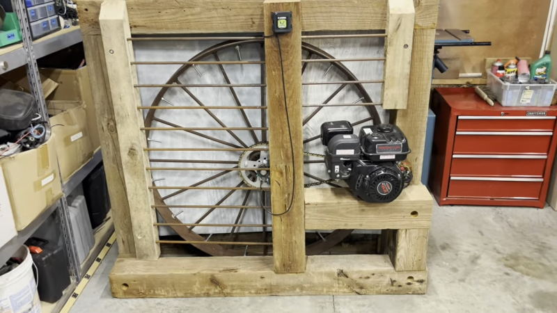
[Lou’s] dynamometer is every bit a DIY project, relying on a 100-year-old wagon wheel as the flywheel installed in a simple frame cobbled together from 6×6 timber beams. As you might imagine, a rusty old wagon wheel probably wouldn’t be in great condition, and that was entirely true here. [Lou] put in the work to balance it up with some added weights, before measuring its inertia with a simple falling weight test. The wheel is driven via a chain with a 7:1 gear reduction to avoid spinning it too quickly. Logging the data is a unit from BlackBoxDyno, which uses hall effect sensors to measure engine RPM and flywheel RPM. With this data and a simple calibration, it’s possible to calculate the torque and horsepower of a small engine hooked up to the flywheel.
Few of us are bench testing our lawnmowers for the ultimate performance, but if you are, a build like this could really come in handy. We’ve seen other dyno builds before, too. Video after the break.


yeah… I mean, this kinda qualifies, like a “butt dyno” qualifies.
I’m a little surprised it would give reasonable results, but I suppose if you do all the measurements and compensate for those, it should work.
I didn’t see how you compensate for the moment of inertia of the engine itself. If the “flywheel” (load) inertia is many times greater then maybe it doesn’t matter.
I suppose it’s a dynamic dynamometer. It accounts for the amount of power available through acceleration, not the power available at some steady RPM which will be more. For that, you need a brake dynamometer.
The difference for a vehicle driven by the engine is how fast you can accelerate up to a speed versus whether you can maintain a speed. As you note, with a purely inertial load, the engine needs to spend some energy to spin itself up, which is subtracted from the amount that can spin the load, so the measured output is always less than what the engine can actually put out.
The error depends on the ratio of the flywheel inertia to the engine inertia. Fortunately, for the size of the thing, inertia scales in the square of the diameter of the wheel you’re spinning, so you can easily have a 100 times more on the flywheel than the engine itself.
Although, the energy stored in a spinning flywheel is also proportional to RPM squared, so gearing it down 7:1 reduces the relative inertia of the wheel to the engine by a factor of 49.
What that means is, when the engine is accelerating, energy is being stored both in the moving parts of the engine and in the flywheel. If the flywheel inertia is 100 times greater, but the engine has to spin 7 times faster, approximately 2 parts of the added energy goes into the flywheel and 1 part in the engine, resulting in a significant error that under-estimates the engine’s power by a third.
So there is the potential for making big mistakes unless the flywheel is truly massive compared to the engine’s spinning parts.
But fortunately, you can account for that as well. If you gun the engine by itself without the flywheel attached, you can observe how fast it accelerates. Then when you add the flywheel with its known inertia (presumably you have measured it), the difference in acceleration will give you how much inertia you have in the engine and the true total output power at each RPM.
If you cannot do that, you can add weights to the flywheel to see how much the situation changes. The total power in the system remains the same in respect to RPM, but the distribution of energy changes depending on the ratio of inertia, so adding weights to the flywheel increases the “efficiency” of the system and the engine appears to be producing more power than it did before.
But, there’s a caveat: combustion engine efficiency also depends on the load at at any given RPM, so your results will vary when you change the inertial load anyways. This is why you need a brake dynamometer, so you can map the engine’s output performance with different loads at the same RPM. Spinning up a simple flywheel doesn’t tell you the whole story.
It’s good that he has RPM sensors on both the engine and the flywheel – you never know when the chain drive ratio will change.
I suppose if you know the rotating inertia, you can determine power and torque by measuring the rate of change of RPM.
(I’m currently sitting about 30 feet from three engine test cells, and if I turn my chair, I can see the engine in the center one – a big red Cummins ISX beast.)
You get to know the power and torque as applied to that particular load. If you then put the engine in a vehicle with a different inertia, the results will be different. How much different? I don’t know.
There’s two cases: what power the engine could apply at each RPM when the load is optimized for that speed and rate of acceleration, and what power the engine does produce at each RPM and acceleration to the actual load. Things like, how fast the pressure changes on the pistons throughout the power cycle changes how efficiently the engine is operating – it’s an impedance matching problem with many variables, which I’m sure you’re familiar with.
Looks like a good way to solve the mystery of gross torque”which seems to have replaced horsepower in small engine ratings. It’s most likely a nonexistent engineering term that can’t be verified in a lab.
The underlying principle of using acceleration verses time in relation to a vehicle would be interesting.
My car has Dino mode on the screen but they forgot to build in a screen freeze so you don’t have to read it at 100mph.
BlackBoxDyno has a Vehicle Mode in settings. It can be attached directly to a vehicle and will measure its torque and horsepower, just like your car, but it captures the data in a graph, like this.
https://youtu.be/9NOXvnTWSJs