If you read about Hall effect sensors — the usual way to detect and measure magnetic fields these days — it sounds deceptively simple. There’s a metal plate with current flowing across it in one direction, and sensors at right angles to the current flow. Can it really be that simple? According to a recent article in Elektor, [Burkhard Kainka] says yes.
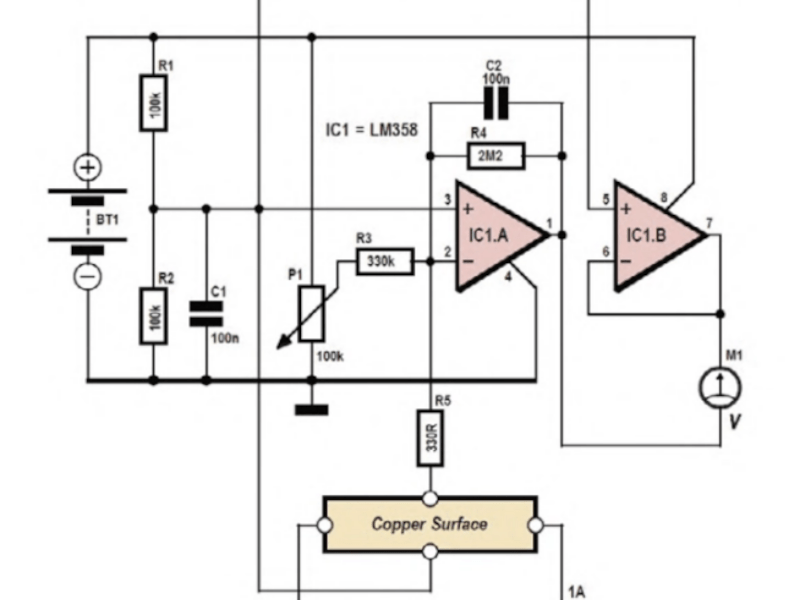
The circuit uses a dual op amp with very high gain, which is necessary because the Hall voltage with 1 A through a 35 micron copper layer (the thickness on 1 oz copper boards) is on the order of 1.5 microvolts per Tesla. Of course, when dealing with tiny voltages like that, noise can be a problem, and you’ll need to zero the amplifier circuit before each use.
The metal surface? A piece of blank PCB. Copper isn’t the best material for a Hall sensor, but it is readily available, and it does work. Of course, moving the magnet can cause changes, and the whole thing is temperature sensitive. You wouldn’t want to use this setup for a precision measurement. But for an experimental look at the Hall effect, it is a great project.
Today, these sensors usually come in a package. If you want to know more about the Hall effect, including who Edwin Hall was, we can help with that, too.


If the magnet is fixed, the output is proportional to current. This leads to a non-resistive (or extremely low resistive) current sensor, and these are also available in small packages.
Such as this one (randomly chosen):
https://www.ti.com/lit/ds/symlink/tmcs1108.pdf?HQS=dis-dk-null-digikeymode-dsf-pf-null-wwe&ts=1766520069309
This particular one is also galvanically isolated.
Pity there’s no link to the Elector article. I was trying to suss out the circuit, but the image is cut off top and bottom. The top line goes straight across – I think – but it would be nice to see the original.
Looks like the battery and resistor dividers provide a +/- supply, the first op amp is a 6666 x inverting voltage amplifier (with offset null adjustment), and the 2nd op amp is apparently (?) a grounded voltage follower.
I don’t know why a 2nd amplifier is needed, maybe it supplies current to drive the voltmeter, or maybe it’s just not needed. It’s not explained in the article.
Can anyone shed light on this?
The article, since it isn’t in the blog post:
https://www.elektormagazine.com/news/circuit-diy-experimental-hall-sensor
Thank you. :)
I wrote a few articles for Elektor a long time ago but I recognized the schematic layout immediately :)
You could also experiment with three layers: magnetized cobalt (foil), copper, and unmagnetized cobalt (foil). Then you would basically have a simple magnetometer (compass).
This experiment was first described here: https://www.elektronik-labor.de/Notizen/Halleffekt.html
The semiconductor-curious may wonder what Cu2O grown on Cu can do in terms of Hall effect structures. It’s intrinsically p-type with low mobility, but forms a Schottky contact against Cu. Contacts made with Pb are ohmic.
It’s been quite a while since I’ve come across it but afaik there’s been variable degrees of interest in making CuxO homo-/heterojunction solar cells over the last few decades. With reasonably low toxicity, no crazy chemicals required and being an oxide that’s stable under atmospheric conditions, it might be worth exploring. Please find a few breadcrumbs below.
Study of Cu2O/Cu Schottky barrier junction
https://researchportal.murdoch.edu.au/esploro/outputs/991005544225807891
HALL EFFECT AND ELECTRICAL CONDUCTIVITY OF Cu2O MONOCRYSTALS
https://doi.org/10.1139/p66-128
I’m a little amazed that the circuit works as described. Deeply suspicious, actually.
Looking for a 1.5 uV signal with a ‘358? With an amp through the copper sensor? While waving a 1T magnet around? Yeesh.
This thing is going to be drifty as heck. And even with the 1 Hz bandwidth that signal is going to be in the grass.
This is not intended for real measurements, but to demonstrate the Hall effect. Similar setups are used for classroom experiments.