One of the perennial challenges of building robots is minimizing the size and weight of drive systems while preserving power. One established way to do this, at least on robots with joints, is to fit each joint with a quasi-direct-drive motor integrating a brushless motor and gearbox in one device. [The 5439 Workshop] wanted to take this approach with his own robot project, but since commercial drives were beyond his budget, he designed his own powerful, printable actuator.
The motor reducing mechanism was the biggest challenge: most quasi-direct drives use a planetary gearbox, but this would have been difficult to 3D-print without either serious backlash or limited torque. A cycloidal drive was an option, but previous printable cycloidal drives seemed to have low efficiency, and they didn’t want to work with a strain-wave gearing. Instead, he decided to use a rope drive (this seems to be another name for a kind of Capstan drive), which doesn’t require particularly strong materials or high precision. These normally use a rope wound around two side-by-side drums, which are difficult to integrate into a compact actuator, but he solved the issue by putting the drums in-line with the motor, with two pairs of pulleys guiding the rope between them in a “C” shaped path.
The actual motor is a hand-wound stator inside a 3D-printed rotor with magnets epoxied into it. The printed rotor proved problematic when the attraction between the rotor and magnets caused it to flex and scrape against the housing, and it eventually had to be reinforced with some thin metal sheets. After fixing this, it reached five Newton-meters of torque at one amp and nine Newton-meters at five amps. The diminishing returns seem to be because the 3D-printed pulley wheels broke under higher torque, which should be easy to fix in the future.
This looks like a promising design, but if you don’t need the output shaft inline with the motors, it’s probably easier to build a simple Capstan drive, the mathematics of which we’ve covered before. Both makers we’ve previously seen build Capstan drives used them to make robot dogs, which says something for their speed and responsiveness.


If there’s no tl;dr then I’m not wasting 15 minutes* on watching incoherent ramblings of some generic content creator.
Why 15 minutes? Gotta please the Might Algorithm or else you’ll be back to manning the public convenience in no time.
You should cut them some slack.
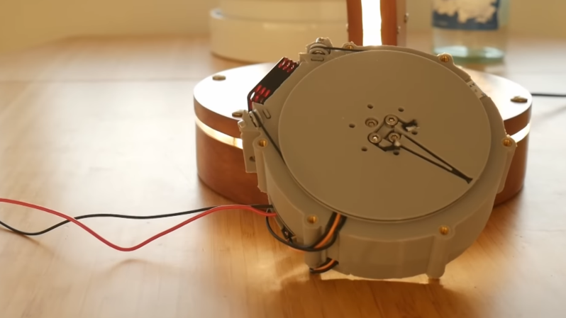
3D printing a brushless motor with intergrated capstan driving a plate on the other side.
Neat idea. I find all the attempts to build compact servos for robotic applications interesting.
Wait for the follow-up video where they fix the immediate problems of this design, start building a robot using the actuator, and then discover that 3D printed plastic also creeps under load, especially when warm, and their motors start to fail soon after they’re put into service.
It’s kinda like how every architect has to design a circular, or a dome, or a pyramid shaped house at some point. They just have to do it, to really grasp why it doesn’t work.
Sure. But prototype in plastic, CNC mill in metal when you have a working design.
I think any slack would prevent a capstan drive working…
TL;DR: yet another youtuber finds out the hard way that 3D printed plastic is not rigid, strong, or hard wearing enough to make a useful servo actuator. Nothing was really accomplished, but the person remains optimistic for the “high potential” of their invention.
Honestly, I’m pretty most of them know this already. But (aside for being more access and quick to produce) 3D prints breaking make great algorithm footage.
Good video; really clear breakdown, summary and clear visuals to help explain the details. Worth a watch if you’ve worked with actuators in robotics.
Hey vän, I think it’s time to make these on a CNC mill :-)