From laser cutters to 3D printers, having an exhaust duct at the back of a machine is a very common sight. However, these tend to be rather bulky, claiming many centimeters of precious space behind a machine even if you’d want to push it right up against a wall. This issue annoyed [TheNeedleStacker] over on YouTube so much that he had a poke at solving this problem with angled exhaust ducts, all hopefully without impairing its basic function.
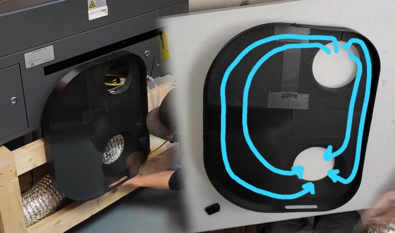
Although there are some online offerings for angled exhaust port extenders, these do not quite fit the required 6″ diameter. Reducing the problem to just a matter of cross section area for simplicity’s sake, that means a 19″ wide duct at a depth of 1.5″. Making sure the transition from the tube to the flat duct doesn’t become an impediment is the tricky part, so the approach here was to mostly ignore it and just make a functional prototype to get an idea of how a direct approach worked.
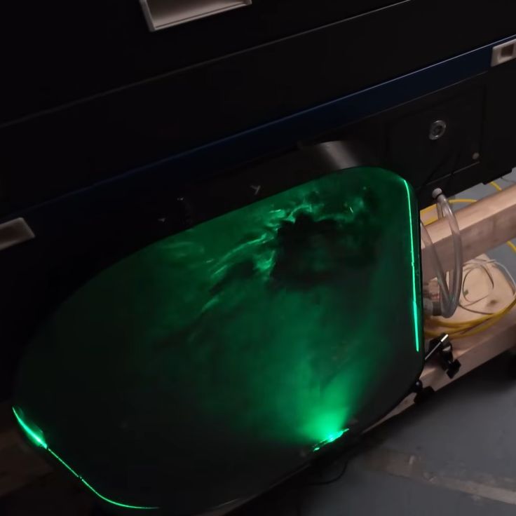
Installing the contraption worked out fine, and subsequent testing showed that although it seems to slightly reduce the effective airflow compared to the flex tubing, it is absolutely rad to look at with the transparent cover and some laser light to illuminate all that’s happening inside.
While some optimization work on the duct transitions can undoubtedly eke out more performance, it’s certainly not bad for a quick project.


(laughs in Bernoulli) would work exactly the same if the whole contraption was just a straight shot down. actually probably a little better since boundary flow is reduced via the reduced internal surface area
I would have just flattened the flexible tube.
But that 59 seconds hack approach is one of the reasons I do not have cool videos with laser visualization.
We made something similar in New Zealand’s Masterton Fab Lab except at the other end of the duct. The idea being to vent out of a window that doesn’t open very far…
So, he’s going to waste the very-obvious passthrough slot on the back of his machine?!
The most beautiful thing about this self-proclaimed quick&dirty one-off project is the choice to make its function observable. If it were on the front, I suspect it would lead to further attempts to tinker around with and improve flow a little more.
A round duct will always have more airflow than a same size square or rectangular duct because of friction inside the duct.There are many online duct calculators, but, here is one of my favorites courtesy of https://www.engineeringtoolbox.com/duct-friction-pressure-loss-d_444.html
Does it calculate the friction from using that stretch-aluminium bendable duct depending on curvature radius, too? /s
Finding the optimum way to close the rectangular cross-section on the tube is very simple. You draw two mirrored involutes around the end of the tube like this:
https://www.researchgate.net/figure/Left-and-right-involute_fig1_364207273
How it works in practice: you take a piece of string and wrap it around the tube. You make a mark on the string, and on the opposite side of the tube, you put a piece of tape on the string so it doesn’t slip. Then you unwrap the string and keep it tight as you do – the mark you made describes the involute curve.
Do it both ways around the tube, and the resulting butt-shaped curve outlines the minimum area you need to leave around the tube to maintain constant cross-section for the transition.
The V-shaped notch of the two involute curves fills in the spot where the air doesn’t need to go, which is opposite of the exit tube. By filling this volume in, you remove the eddies and swirls that would form there and disrupt the smooth flow of air towards the desired direction.