Oscilloscopes and to lesser extent signals generators are useful tools for analyzing, testing and diagnosing circuits but we often take for granted how they work. Luckily, [FromConceptToCircuit] is here to show us how they’re made.
[FromConceptToCircuit] starts by selecting the hardware to use: an Artix-7-based FPGA and an FT2232 USB-serial converter. RS245 in synchronous FIFO mode is selected for its high bandwidth of about 400 Mbps. Then, they show how to wire it all up to your FPGA of choice. Now it’s time for the implementation; they go over how the FT2232 interfaces with the FPGA, going through the Verilog code step-by-step to show how the FPGA makes use of the link, building up from the basic transmission logic all the way up to a simple framed protocol with CRC8-based error detection. With all that, the FPGA can now send captured samples to the PC over USB.
Now it’s PC-side time! [FromConceptToCircuit] first explains the physical pipeline through which the samples reach the PC: FPGA captures, transmits over RS245, FT2232 interfaces that with USB and finally, the software talks with the FT2232 over USB to get the data back out. The software starts by configuring the FT2232 into RS245 mode, sets buffer sizes, the whole deal. With everything set up, [FromConceptToCircuit] explains how to use the FT2232 driver’s API for non-blocking communication.
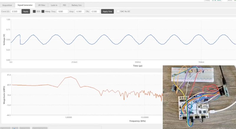
As a bonus, [FromConceptToCircuit] adds a signal generator feature to the oscilloscope using an I2C DAC chip. They start by explaining what exactly the DAC does and follow up with how it’ll be integrated into the existing system. Then it’s time to explain how to implement the I2C protocol bit-for-bit. Finally combine everything together for one final demo that shows a sine wave on the DAC’s output.


(Is that supposed to be FT245? I haven’t run into FT245 before either, but can’t find anything on RS245.)
Seems to be somewhat incorrectly written. From FTDI´s documentation, ” …. The FT2232H only channel A can be configured as a FT245 style synchronous FIFO interface. ” …
They work becasue they have physical knobs we can turn and physical buttons we can push while we’re diagnosing the circuit.
For decades people have been trying their luck with primitive ATmega8 MCUs and Nokia 3310 screens, STM32s and chinese color LCDs, Bluetooth chips paired with Android “apps” on a large tablet screen, FPGAs connected to PCs and every single time the result is far less useful than a humble Rigol DS1052E.
yeah the two things i love about my Siglent SDS1102 are the physical knobs (knobs!!!) and the analog front-end with like voltage auto-ranging. 6 knobs: zoom / offset for channel 1, channel 2, and time. Just amazing usability compared to the buttons-and-menus scope i used to have, or anything i could imagine on a PC or android interface.
USB scopes are handy for portable use. I definitely want knobs and switches at the bench though.
Try using the autel scope for automotive diag. Wish I had what you guys had. Any tips lol.
Ds1054z is this a good one to buy
A bit dated, but I still have mine and it’s proven really useful over the years… I don’t know the budget, but modern alternatives have faster and better analysis, on top of quite a few extra bits of resolution… FFT on the DS1054Z is barely a toy, as are math functions, but advanced triggering is ways better compared to any usb or handheld scope I’ve used.