When building a project to operate on battery power for long periods of time, having a microcontroller with a reliable and extremely low-power sleep mode is critical. When processing power isn’t needed, it should be able to wait around using almost no energy until an interrupt triggers it. Once triggered, the CPU performs its tasks and then puts itself right back to sleep, making sure the battery lasts as long as possible. Unfortunately, not every microcontroller has sleep capabilities or has an acceptably low level of power use for maximizing battery life. For these systems, a tool like this power manager might come in handy.
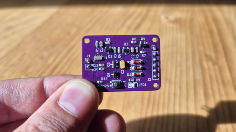
The small PCB, called the powerTimer, essentially acts as a middleman for power delivery to another microcontroller. On the PCB is an RV3028-C7 real-time clock, which uses a mere 45 nA of current and can interact with the second microcontroller through a timer or alarm. When commanded, the powerTimer uses an SR latch as its main control circuit, allowing single button presses to change the power state for the second microcontroller. Once the powerTimer powers up the second microcontroller, that microcontroller can communicate back to the powerTimer with a “DONE” signal, and once this signal is received, the powerTimer will cut power and wait for the next interrupt to occur.
The project’s creator, [Juan], had this idea for an ESP32 with a camera module. While it does have a sleep mode, the ESP32 wasn’t nearly low-power enough to get the battery life that he wanted. With a modular system like this, it can be used in many other applications as well. PowerTimer is one of the entries in our 2026 Green Powered Challenge.


If you just want a button press or a fixed timer elapsing to power on your circuit, TPL5111 is a great choice. I have used it in a project at work, and its really quite good with only one other component (a resistor) needed to set its sleep period. Quiescent current is 35nA
TPL5110 is another, or other 5xxx variants depending on what you want it to do. There’s power gate clocks, watchdogs, etc. The only downside is that you have to fix the time period by a resistor, and that’s not going to be very exact.
Well, for a one off you can calibrate the timing to the desired time by changing the resistance untill you’re happy.
In theory. The chip measures the resistor on boot and digitizes the value, so the time you get is subject to ADC noise and quantization. You don’t get all possible timing values.
What you could do is add a programmable resistor (I2C etc.) and bypass the FET gate drive with a simple OR circuit to keep the power on, then use another FET to power cycle the timer to reprogram it on the fly. If the timing drifts, you change the resistance value slightly to make it drift the other way, and then back again.
For a button press, i’d use the button to close the circuit.
With the exception of the ESP32-C3, most flavors of ESP32 has the ULP co-processor that is intended to be able to do things like manage the uC power domains entirely in software.
http://docs.espressif.com/projects/esp-idf/en/stable/esp32/api-reference/system/ulp.html
Of course, this ULP approach only is applicable if you are building a project from source code where the assembly code for the ULP can be added.
As an early ESP user, I found that the ESP microcontrollers were great for replacing anemic SRAM/Flash Arduino boards in non-wireless projects simply by disabling the WiFi power domain.
Example below is 10+ years old, so consider it pseudo-code until the latest Espressif files are consulted.
// ESP8266
#include <ESP8266WiFi.h>
void setup() {
WiFiMode(WIFI_STA);
WiFi.disconnect();
WiFi.mode(WIFI_OFF);
}
Newer esp32 series chips have moved from the custom ulp architecture to a small low power risc-v core for that
The ULP core still consumes 2 orders of magnitude more power than 45nA.
True, but probably totally irrelevant if your application needs to power the full ESP32 and a camera periodically. If you have e.g. a 1Ah battery and you are drawing 10uA in deep sleep, the battery will already last for 100’000h in deep sleep, that’s like 10 years. At that point, usually only the active periods play a relevant role for the battery life.
That 45nA timer is really interesting, if you are drawing very little power also during active periods, and you can hence power your device from a coin cell.
In practice your other power circuitry before the timer (capacitors, self-discharge etc. ) will be leaking 10+ µA anyways unless you pay special attention to that. If you don’t want to spend the extra effort, using a better timer can still significantly improve your standby time.
There’s an order of magnitude more in ESP32’s ULP consumption compared to this RV3028-C7 chip. The ESP’s ULP is in the tens of µA range, while this chip is in the tens of nA range. At that range, the loss in the power supply chain (DC/DC or LDO / coin cell) will be much higher than anything else and will condition the lifetime of your product, not the chip itself.
The ESP itself can deep sleep at 8uA provides you don’t need things like gpios to stay powered.
From what i understand, the ESP32 is kinda the new Arduino; rather capable and not especially low-power, no?
Not when active, certainly. But it’s also something of a kitchen sink device. In sleep it’s not the lowest of the low, but it is fairly reasonable
I’ve always just used an Arduino ATmega328P microcontroller for super low powered needs. The ATmega only uses 60μA in deep sleep that can be woken by a timer or a pin signal. I’ve created projects that have run for years on a set of 4 AA batteries. No need for a separate circuit.
60 µA is still roughly 500 mAh per year. The question becomes, what else does it do besides sleep?
60uA for deep sleep is really high these days.
An ESP32 has a deep sleep current of ~8uA.
60uA also 3 orders of magnitude more current than this circuit at 45 nA
For sensor based wakeup, the nanopwer nPZero is ideal. https://dev.nanopowersemi.com/core_docs/NPZ_G1S_DS_V0_95___datasheet.pdf
Given the ESP32CAM boards is likely to have regulators with high quiescent currents, this is the best solution they could put together without generating masses more work – given designing and building an ESP32CAM board isn’t an easy task. I reckon that makes it a hack.