The Cutting Truth About Variable Capacitors

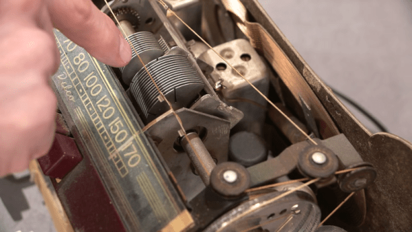
If you’ve seen a big air-variable capacitor, you may have noticed that some of the plates may have slots cut into them. Why? [Mr Carlson] has the answer in the video below. The short answer: you can bend the tabs formed by the slots to increase or decrease the capacitance by tiny amounts for the purpose of tuning.

For example, if you have a radio receiver with a dial, you can adjust the capacitor to make certain spots on the dial have an exact frequency. Obviously, you can only adjust in bands depending on how many slots are in the capacitor. Sometimes the adjustments aren’t setting the oscillator’s frequency. For example, the Delco radio he shows uses the capacitor to peak the tuning at the specified frequency.

You usually only find the slots on the end plates and, as you can see in the video, not all capacitors have the slots. Of course, bending the plates with or without slots will make things change. Just don’t bend enough to short to an adjacent plate or the fixed plates when the capacitor meshes.

Of course, not all variable capacitors have this same design. We’ve seen a lot of strange set ups.

Continue reading “The Cutting Truth About Variable Capacitors” →
Jon Peddie’s The Graphics Chip Chronicles On Graphics Controller History

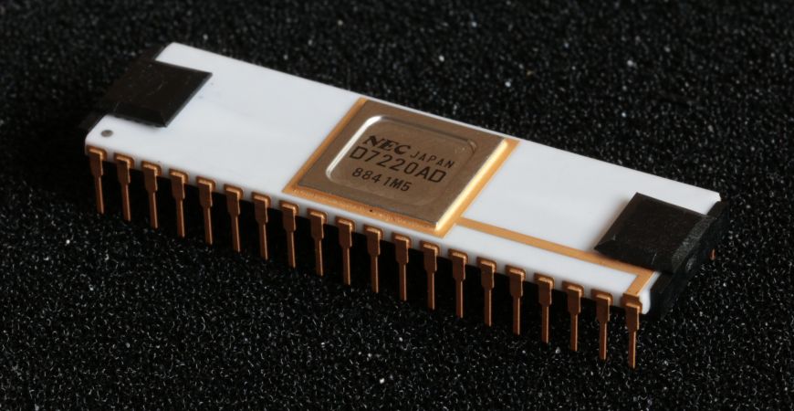
Using computers that feature a high-resolution, full-color graphical interface is commonplace today, but it took a lot of effort and ingenuity to get to this point. This long history is the topic of [Dr. Jon Peddie]’s article series called The Graphics Chip Chronicles. In the first of eight volumes, the early days of the NEC µPD7220 and the burgeoning IBM PC.

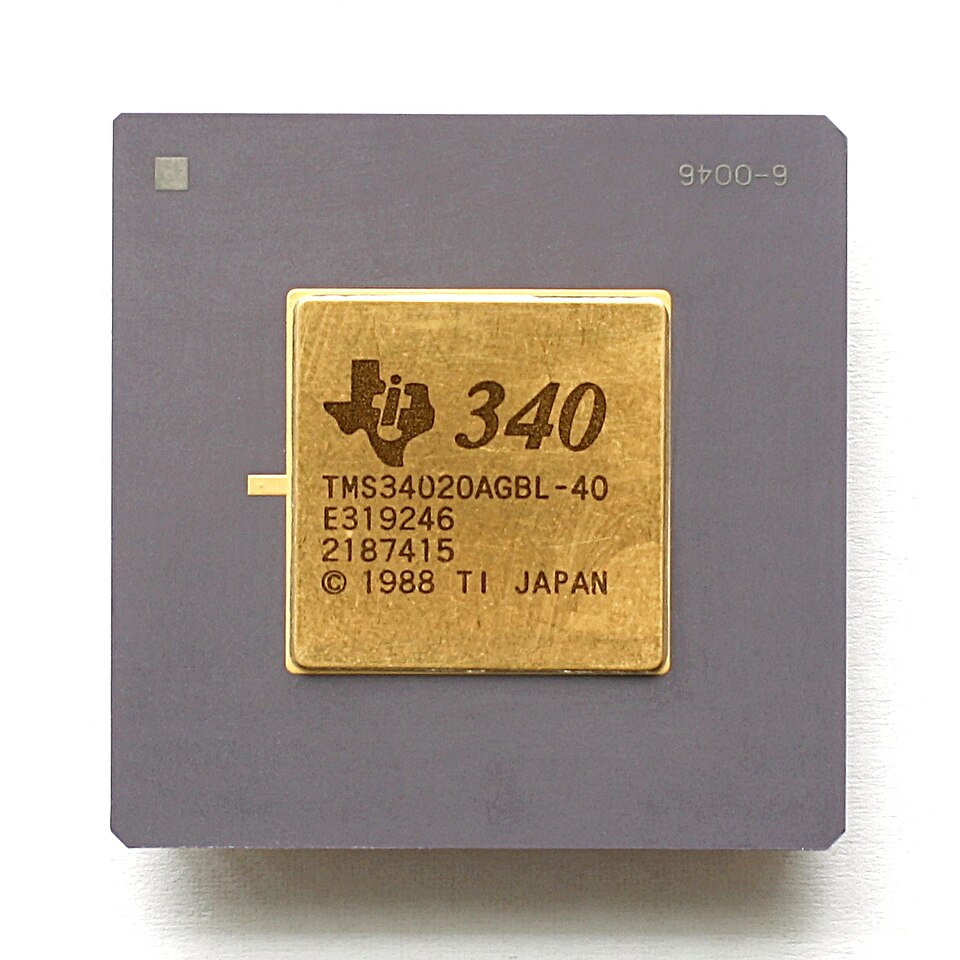
Texas Instruments TMS34020 (Source: Wikimedia)

These are just brief overviews of these particular chips, of course, with a lot more detail to be found when you go digging. Details such as the NEC µPD7220 being the graphics chip in Japan’s PC-9800 series of computers which are famous for the amazingly creative art and games that this chip enabled.

While the average Hackaday reader is likely familiar with the IBM PC side of things, Texas Instruments’ graphics controllers, including the very interesting TMS34010 and successor TMS34020 which can be called the first proper graphical processing units, or GPUs, effectively a CPU with graphics-specific instructions.

Although it’s tempting to see computer graphics as a direct line from the days of monochrome graphic controllers to what we have today in our PCs, there were a lot of companies and countless talented individuals involved, including companies who built clones that would go on to set new standards. If you’re into reading through a few years worth of computer history articles by someone who has been in the industry for even longer, it’s definitely worth a read.

Thanks to [JohnS_AZ] for the tip.


Top image: NEC µPD7220 by Drahtlos – Own work, CC BY-SA 4.0)

Trace Tracing To The Tunes

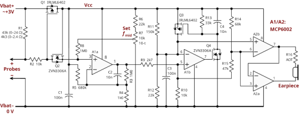
Some kind of continuity beeper has been a standard piece of gear since the dawn of electronics. Sure, you probably have an ohm meter, but sometimes you don’t care about the actual resistance. You just want to know whether something connects or doesn’t, especially with a PCB trace or a cable. But what if your beeper could tell you more? [Nick Cornford] asks and answers that question with a beeper that lets you estimate resistance via pitch.

The circuit is relatively simple. A short to ground causes a voltage divider to produce a fraction of the battery voltage and a FET to conduct that fractional voltage to a VCO via a high-gain amplifier. The VCO converts voltage to frequency, and an audio amplifier feeds it to the speakers.

The two amplifiers and the VCO require two dual op-amp chips. The original schematic sends the output to some relatively high-impedance headphones. To drive more practical ones, the circuit can drop one op amp and use another FET and a separate battery.

Of course, you have many design choices, especially for the audio amplification. There are plenty of VCO circuits, or you could probably substitute a small microcontroller with an A/D converter and PWM output. Yes, you can also make a VCO with a 555.

VCOs are common because they are at the heart of PLLs.