Every experienced machinist knows the value of taking regular measurements. If one works carefully and checks dimensions frequently, it’s possible to make a part much more precise than could be made by relying on the machine’s accuracy alone. In a similar vein, it’s possible to make a measuring device out of comparatively crude parts, as long as their behavior is well understood. Related to both principles is [BubsBuilds]’s displacement sensor, which uses a 3D printed frame but reaches precision better than two micrometers.
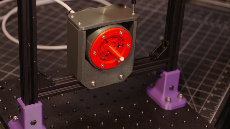
Admittedly the printed parts aren’t the source of the sensor’s precision, that comes from an opto-interrupter. This design has a central stylus, one end of which contacts the object under measurement. The other end flattens to a knife-edge blade, which fits between the diodes of the opto-interrupter. As the stylus point is pressed in, the blade blocks off more light from reaching the photodiode, creating an output signal proportional to displacement. To keep the stylus from twisting or moving side-to-side, two flat, circular flexures hold the stylus in the center of a cylindrical housing.
[Bubs] printed several flexure variations to see how well they resisted and permitted various torques and forces, and a symmetrical flexure design proved best for his purposes. Once the sensor was assembled, he tested it against the measurements recorded by a laser confocal displacement sensor. This design was an update from a previous version, and it improved in a few regards: the non-linearity had decreased, and the repeatability was now better than two microns, though the range had been halved. Significantly, though, it’s now much easier to mount, making this an actually practical tool.
If, however, this doesn’t fit your needs, there are many other ways to build a linear displacement sensor, ranging from capacitive to magnetostrictive. On the manual side of things, we’ve also covered a comparison of calipers.


Makes me wonder if I can configure and tune a common optointerrupter type sensor (as salvaged from copiers, printers and the like over the years) to detect a small displacement like the thickness of an adhesive label (sensing the gap, essentially) still on its roll of release liner.
Op-amp or other high gain thingies likely required. Maybe just a ‘393 like found in old trackball controllers I’ve messed with. I guess most of the circuitry needed is there, like the one-shot to debounce edge detection.
Label printers usually already have that built in, to determine when there’s a label present at the correct position to print, but they are looking for opacity changes rather than thickness. Possible yes, but calibration might be somewhat difficult, a plastic wedge is nice and uniform, paper or plastic labels are not, at least not at the scales you’d likely be hoping to measure. The manufacturer’s datasheet is probably the easier route. Counting labels without transfering them to a new role isn’t straight forward, diameter, weight, it’s all fairly error prone.
If someone were obsessed with automatic bed-leveling in FDM printing this could turn into quite a useful idea to replace the usual contact switches as a feedback mechanism, even at a lower level of accuracy/sensitivity/precision.
I wonder how well these springs would deal with a vertical mounting so they’re always hanging in tension in the same direction and creeping. I guess the only thing that matters is the knife edge to diode geometry so sag probably doesn’t matter. This seems attractive to use for a tool length sensor in a cnc mill.
I wonder how well the spring could measure gravity when mounted vertically. Walk up a mountain and see the difference, replace the opto isolator with a photomultiplier tube and feel trucks passing outside perhaps, then I guess you’d be limited by creating a stable light source.
Maybe just stick some tinfoil underneath and measure the capacitance.