
Unlike biological systems, which can use muscles, robots that try to imitate them don’t have particularly fast, powerful, compact linear actuators available. This puts walking robots at a particular disadvantage, since they can’t spread their actuators along a limb and have to place them right at the joint. [Food for Robots] took on the challenge of building such a joint-mounted actuator, and shared the results in a recent video.
[Food for Robots] is building a walking robot, so he needed a compact, lightweight, and backdrivable actuator capable of producing 20 Newton-meters of torque. He’d previously built a largely 3D-printed actuator, but when he tried to exceed 10 Nm of torque with it, various parts kept breaking. He therefore machined the second iteration out of aluminum; since it didn’t need to be 3D printed, he switched from a Capstan drive to a planetary gearbox. The gearbox sits in the center of the actuator, inside the stator, and uses several stacked layers of gears to increase strength within the limits of a small CNC.
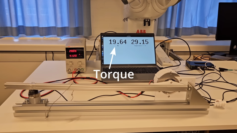
The back of the motor’s rotor holds a small magnet, and the control board uses it to read the position. [Food for Robots] reused the controller from the earlier actuator. In the first test, the actuator didn’t pass 10 Nm of torque, despite doubling the stator’s thickness. After some investigation, [Food for Robots] found that increasing the number of windings hadn’t increased power, since it had cut the number of wires used and thus increased resistance. However, increasing the current limits in the field-oriented control algorithm did let it reach 20 Newton-meters.
For a few other quasi-direct drive actuators, check out some of the other great builds we’ve featured.











reinvent the 1980s technology of industrial robots.
btw. the whole video is pretty much an advert of some chinese PCB manufacturer so don’t waste your time watching it.
I totally agree. It’s basically a year of design to create a sub par version of a COTS product.
And to save him from another year of disappointments: 7075 is not fit for gears. It does not have nice friction / wear properties. And on top of that, blowing unfiltered cooling air though the gearbox (@13:25) is another bad idea. Dust and other particles will stick to the oil / grease and make the wear much worse. It may be fine for a prototype and experiments, but it won’t last in this configuration.
After looking around for 3 minutes, I found “QDD” which stands for “Quasi Direct Drive”
https://duckduckgo.com/?q=qdd+actuator&iar=images&t=h_
And that really should be (is) common knowledge for people interested in this sort of motor control.
But still, the road to getting there may be interesting to some. There are plenty of good reasons for designing the whole drive system like this, and some people have to stumble on each step to get there.
And another (3rd!) mistake I saw earlier in the video. The “teeth” on the rotor lamination plates to keep the magnets apart are badly designed. They suck up a part of the magnetic field that should go into the stator. The better motors use a hallbach array in that location.
And with that, my advise to this guy becomes: Get out of your own backyard and look around you. All the mistakes you made have already been made 100 times over by other people before you.