Folding Robots With Special Materials

When it comes to robots, we usually see some aluminum extrusion, laser-cut parts, maybe some 3D printed parts, and possibly a few Erector sets confabulated into a robot arm. This entry for the Hackaday Prize is anything but. It’s a robot chassis, a 3D printer, and the structural frame for any sort of moving project that’s made out of a special composite material.

[Marc]’s project for the Hackaday Prize is all about articulated mechanisms. Instead of the usual structural components, he’s using Hylite, a special material that’s basically a polypropylene core clad in a sheet of aluminum on both sides. By carefully milling away the aluminum on both sides, [Marc] is creating a living hinge that can be used to build a 3D printer, robot, or really anything else.

This really isn’t a finished project; it’s more of a technology demonstrator. That said, [Marc] has a lot of examples where he can bend these Hylite aluminum plates over on themselves, can create boxes and space frames, and has the ability to create just about any shape he wants. It’s really a highly precise means of bending aluminum with a mill, and has the added benefit of looking really, really good.

Already, [Marc] has a few interesting robots that are built around this construction technology. The first is a remote control focus for a telescope that simply connects an eyepiece to the scope. Actuation is provided pneumatically, and all reports say this example works well. The other example is a flat-pack phone stand. It’s a bit simpler than a focus mechanism, but it is a small and inexpensive way to show off the technology. Great work, and an excellent project in The Hackaday Prize.

Friday Hack Chat: All About The Hackaday Prize

Right now we’re neck deep in the Hackaday Prize. What’s the Hackaday Prize? It’s the Academy Awards of hardware creation, or at least that’s what we’re calling it until we get a cease and desist from the Academy of Motion Picture Arts and Sciences.

Already we’ve seen over eight hundred entries in the Hackaday Prize, and there are still months to go. We’re already through the Open Hardware Design Challenge, and twenty fantastic projects from that are moving onto the final round. Yesterday, we announced the winners of the Robotics Module challenge, and again we were blown away. These are the greatest bits of hardware anywhere, and we couldn’t have imagined anything more awesome.

For this week’s Hack Chat, we’re going to be talking all about The Hackaday Prize. This is your chance to be a hardware hero and finally get some recognition for what you’ve been working on. Right now, we’re in the Power Harvesting Challenge in this year’s Hackaday Prize, and we want to see what you can come up with that will get energy from solar, thermal, wind, or random electromagnetic energy. This is your time to shine, and we can’t wait to see what you come up with.

Of course, you might have a few questions on what it takes to make a successful Hackaday Prize entry. For this week’s Hack Chat, we’re going to sit down with [Stephen Tranovich], the person coordinating this year’s Prize, to see what makes a successful entry. This is your chance to find out what it takes to become the next great hardware hacker, and it’s all going down this Friday in the Hack Chat.

Some of the things we’ll be talking about in this week’s Hack Chat:

  • What makes a winning entry?
  • How can you get publicity for your project?
  • Want to bounce your project ideas off the community?
  • What’s the story behind the seed funding confusion from this year?

You are, of course, encouraged to add your own questions to the discussion. You can do that by leaving a comment on the Hack Chat Event Page and we’ll put that in the queue for the Hack Chat discussion.join-hack-chat

Our Hack Chats are live community events on the Hackaday.io Hack Chat group messaging. This week is just like any other, and we’ll be gathering ’round our video terminals at noon, Pacific, on Friday, June 15th.  Here’s a clock counting down the time until the Hack Chat starts.

Click that speech bubble to the right, and you’ll be taken directly to the Hack Chat group on Hackaday.io.

You don’t have to wait until Friday; join whenever you want and you can see what the community is talking about.

These Twenty Amazing Projects Won The Robotics Module Challenge

Right now, we’re running the greatest hardware competition on the planet. The Hackaday Prize is the Academy Awards of Open Hardware, and we’re opening the gates to thousands of hardware hackers, makers, and artist to create the next big thing.

Last week, we wrapped up the second challenge in The Hackaday Prize, the Robotics Module challenge. Now we’re happy to announce twenty of those projects have been selected to move onto the final round and have been awarded a $1000 cash prize. Congratulations to the winners of the Robotics Module Challenge portion of the Hackaday Prize. Here are the winners, in no particular order:

Robotics Module Challenge Hackaday Prize Finalists:

These projects are fantastic

These are the best projects the Robotics Module Challenge in this year’s Hackaday Prize has to offer. These projects are simply fantastic. You answered the call with more than 200 entries for this challenge, and have created the best projects that can be turned into smarter, better robots. Need some proof? Just take a look at some of these projects. Continue reading “These Twenty Amazing Projects Won The Robotics Module Challenge”

PCBs As Linear Motors

PCBs are exceptionally cheap now, and that means everyone gets to experiment with the careful application of copper traces on a fiberglass substrate. For his Hackaday Prize entry, [Carl] is putting coils on a PCB. What can you do with that? Build a motor, obviously. This isn’t any motor, though: it’s a linear motor. If you’ve ever wanted a maglev train on a PCB, this is the project for you.

This project is a slight extension of [Carl]’s other PCB motor project, the aptly named PCB Motor. For this project, [Carl] whipped up a small, circular PCB with a few very small coils embedded inside. With the addition of a bearing, a few 3D printed parts, and a few magnets, [Carl] was able to create a brushless motor that’s also a PCB. Is it powerful enough to use in a quadcopter? Probably not quite yet.

Like [Carl]’s earlier PCB motor, this linear PCB motor follows the same basic idea. The ‘track’, if you will, is simply a rectangular PCB loaded up with twelve coils, each of them using 5 mil space and trace, adding up to 140 turns. This is bigger than the coils used for the (circular) PCB motor, but that only means it can handle a bit more power.

As for the moving part of this motor, [Carl] is using a 3D printed slider with an N52 neodymium magnet embedded inside. All in all, it’s a simple device, but that’s not getting to the complexity of the drive circuit. We’re looking forward to the updates that will make this motor move, turning this into a great entry for The Hackaday Prize.

Ask Hackaday: What Color Are Your PCBs?

A decade ago, buying a custom-printed circuit board meant paying a fortune and possibly even using a board house’s proprietary software to design the PCB. Now, we all have powerful, independent tools to design circuit boards, and there are a hundred factories in China that will take your Gerbers and send you ten copies of your board for pennies per square inch. We are living in a golden age of printed circuit boards, and they come in a rainbow of colors. This raises the question: which color soldermask is most popular, which is most desirable, and why? Seeed Studio, a Chinese PCB house, recently ran a poll on the most popular colors of soldermask. This was compared to their actual sales data. Which PCB color is the most popular? It depends on who you ask, and how you ask it.
Continue reading “Ask Hackaday: What Color Are Your PCBs?”

Hackaday Links Column Banner

Hackaday Links: Benchoff Rants On Flying Cars

It’s time for Computex, and that means [Linus] has dropped something. I don’t know what, but he’s dropped something. It’s a meme or something at this point. What were the highlights? Asus announced Project Precog, a laptop with two screens. Yes, a touchscreen keyboard. It’s the 2018 version of the IBM Transnote or whatever that Microsoft thing was called. Why is it called Project Precog? Because AI or whatever. Unimaginative marketing is terrible. Intel is going to launch a 28-core CPU, and AMD is introducing a 32-core CPU. Awesome, core wars. And here’s RGB RAM because stuffing a case full of cold cathode lighting is sooo early-2000s.

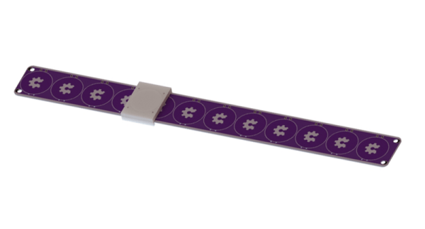
Need a reverse engineering challenge? Here’s something from American Science and Surplus. It’s a 48 x 12 LED matrix, loaded up with driver ICs and power regulators. $20 a piece, so stock up and save.

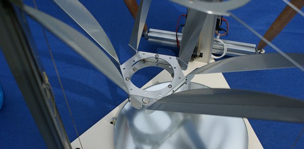
Finally, the main event. The biggest story in aviation this week is that a media embargo has lifted on the Kitty Hawk Flyer. Kitty Hawk is a startup funded by Larry Page, CEO’d by Sebastian Thrun, and has received $6.5 M in funding. The Flyer, a one-man decacopter, was announced to the world through CNN Money and Casey Neistat. It should be noted that in the entire media landscape, these are the two outlets most ignorant of aviation: CNN needs no explanation, and Neistat flies quadcopters through the Hudson River Corridor at 1000 feet AGL. Additionally, Kitty Hawk is not exhibiting at AirVenture next month, which leads me to believe Kitty Hawk is trying to stay out of the aviation industry or simply doesn’t want knowledgeable people asking them questions. But I digress.

The Kitty Hawk Flyer is being promoted by the company as “a personal flying vehicle… to make flying part of everyday life” and a machine that will give you, “a world free from traffic”. It is being billed by CNN and Neistat as ‘a flying car’. Kitty Hawk is just fine with allowing the media to call it as such. Additionally, Sebastian Thrun is making claims about the Flyer that are disingenuous at best, outright illegal at worst, and should draw the ire of any investors.

In the CNN Money piece, Thrun claims the Flyer is capable of traveling at 100 miles per hour, which would be illegal. The Flier is certified as a Part 103 Ultralight, and under that regulation the Flyer “is not capable of more than 55 knots calibrated airspeed at full power in level flight.” The Flyer may also be overweight. The first version of the Flyer was basically a decacopter with a seat, and weighed in at 220 pounds. Part 103 regulations have a limit of 254 pounds, and it’s entirely possible there are more than 34 pounds of chassis and fiberglass on the latest version. I should also mention the safety training, while not required for a Part 103 ultralight, is insufficient: Casey Neistat’s underwater egress training was done in a Chuck E. Cheese-style ball pit. You can breathe in a ball pit, you can’t breathe underwater.

But legality aside, a Part 103 ‘flying car’ is just about the dumbest idea ever. You can’t use it to commute, and you’re welcome to call your local FSDO to confirm that. You’re not going to fly it in New York City or San Francisco because there are airports in the way. At best, this is a ‘flying ATV’ that you would take out on your farm; a toy for rich people. At worst, it’s the latest example of the Silicon Valley philosophy of ‘ignore laws and break things’.

Super Chromatic Peril Sensitive Sunglasses

The Joo Janta 200 super-chromatic peril-sensitive sunglasses were developed to help people develop a relaxed attitude to danger. By following the principle of, ‘what you don’t know can’t hurt you,’ these glasses turn completely opaque at the first sign of danger. In turn, this prevents you from seeing anything that might alarm you.

Here we see the beginnings of the Joo Janta hardware empire. For his Hackaday Prize entry, [matt] has created Nope Glasses. Is that meeting running long? Is your parole officer in your face again? Just Nope right out of that with a wave of the hand.

The Nope Glasses are two LCD shutters mounted in a pair of 3D printed glasses. On the bridge of the glasses is an APDS 9960 gesture sensor that tracks a hand waving in front of the glasses. Waving your hand down in front of the glasses darkens the shutters, and waving up makes them clear again. Waving left flashes between clear and dark, and waving right alternates each shutter.

In all seriousness, there is one very interesting thing about this project: how [matt] is attaching these LCD shutters to his glasses. This was done simply by taking a picture of the front and top of his glasses, converting those to 1-bit BMPs, and importing that into OpenSCAD. This gave him a pretty good idea of the shape of his glasses, allowing him to create an ‘attachment’ for his glasses. It’s great work, and we’d really like to see more of this technique.