Modular Rover Platform Rolls On 3D Printed Flexible Tank Tracks

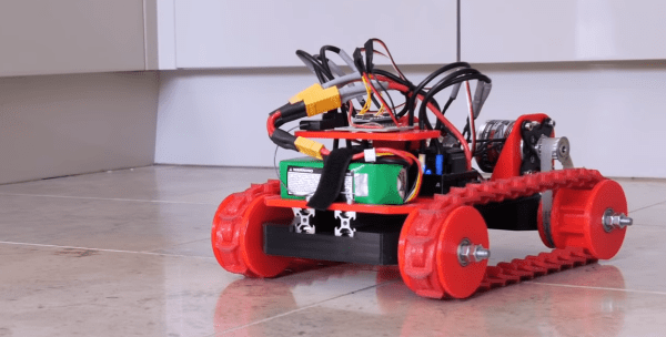
Master of 3D printed robots, [James Bruton], plans to do some autonomous rover projects in the future, but first, he needed a modular rover platform. Everything is cooler with tank tracks, so he built a rover with flexible interlocking track sections.

The track sections are printed with flexible Ninjaflex filament. Each section has a tab designed to slot through two neighboring pieces. The ends of the tabs stick through on the inside of the track fit into slots on the drive wheel like gear teeth. This prevents the track from slipping under load. The Ninjaflex is almost too flexible, allowing the tracks to stretch and almost climb off the wheels, so [James] plans to experiment with some other materials in the future. The chassis consists of two 2020 T-slot extrusions, which allows convenient mounting of the wheel bogies and other components.
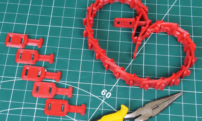
The interlocking track pieces

For initial driving tests [James] fitted two completely overpowered 1500 W brushless motors that he had on hand, which he plans to replace with smaller geared DC motors at a later stage.

A standard RC system is used for control, but it does not offer a simple way to control a skid steer vehicle. To solve this, [James] added an Arduino between the RC receiver and the motor ESC. It converts the PWM throttle and turn signal from the transmitter, and combines is into differential PWM outputs for the two ESCs.

Continue reading “Modular Rover Platform Rolls On 3D Printed Flexible Tank Tracks”

A Geared Bench Vise To Clamp All The Things

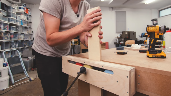
On the eternal quest of workshop upgrades, [Alexandre Chappel] has combined woodworking and 3D printing to add a versatile 0.5 m wide vise with some clever internals to his workbench.

The challenge with such a wide vise is that it requires two timed lead screws on either end of the vise to prevent if from pulling skew under force. This can be done with a chain, belt, or [Alexandre]’s choice, gears. Inside the moving part of the vise he fitted series of 5 herringbone gears. By turning the center gear with a lever, it rotates the gears on the end which are fixed to tow lead screws. The external surfaces of the clamp are made with plywood, and the gears are printed with PLA and high infill percentage. [Alexandre] does say that he is not sure durable the gears are, but they definitely aren’t flimsy. He added an acrylic inspection window to the box section, which we think looks superb with the colored gears peaking through. The back of the vise is mounted inside the workbench, which keeps the look clean and doesn’t take up any bench space.

[Alexandre] does a lot of filming in his workshop, so recently he also built a very impressive and practical camera arm to avoid having to move tripods the whole time. A vise is a must-have tool in almost any workshop, so we’ve seen a few DIY versions, like magnetic base vise and one with a hydraulic vise.

3D Printed SCARA Arm With 3D Printer Components

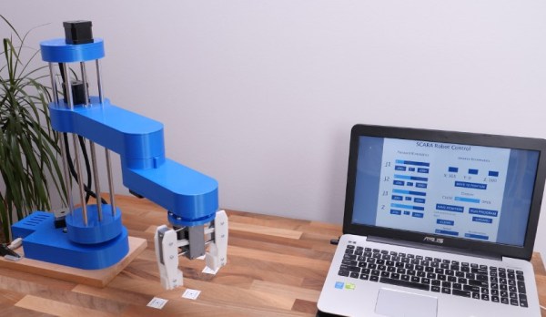
One of the side effects of the rise of 3D printers has been the increased availability and low cost of 3D printer components, which are use fill for range of applications. [How To Mechatronics] capitalized on this and built a SCARA robot arm using 3D-printed parts and common 3D-printer components.

The basic SCARA mechanism is a two-link arm, similar to a human arm. The end of the second joint can move through the XY-plane by rotating at the base and elbow of the mechanism. [How To Mechatronics] added Z-motion by moving the base of the first arm on four vertical linear rods with a lead screw. A combination of thrust bearings and ball bearings allow for smooth rotation of each of the joints, which are belt-driven with NEMA17 stepper motors. Each joint has a microswitch at a certain position in its rotation to give it a home position. The jaws of the gripper slide on two parallel linear rods, and are actuated with a servo. For controlling the motors, an Arduino Uno and CNC stepper shield was used.

The arm is operated from a computer with a GUI written in Processing, which sends instructions to the Arduino over serial. The GUI allows for both direct forward kinematic control of the joints, and inverse kinematic control,  which will automatically move the gripper to a specified coordinate. The GUI can also save positions, and then string them together to do complete tasks autonomously.

The base joint is a bit wobbly due to the weight of the rest of the arm, but this could be fixed by using a frame to support it at the top as well. We really like the fact that commonly available components were used, and the link in the first paragraph has detailed instructions and source files for building your own. If the remaining backlash can be solved, it could be a decent light duty CNC platform, especially with the small footprint and large travel area. Continue reading “3D Printed SCARA Arm With 3D Printer Components”

Scratch-Built XY Table Gets The Job Done

Unless you have one large pile of cash to burn through, properly equipping a workshop can take years of burning through little piles of cash. Whether to save a bit of cash or simply for the challenge, [Workshop from Scratch] is doing exactly what his channel name suggests, and his latest project is a XY table. (Video, embedded below.)

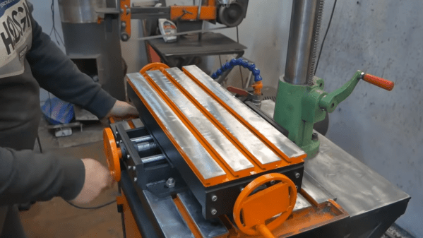
A XY table, or cross table, allows a workpiece to be translated in two dimensions, usually on a drill press or milling machine. On a drill press they make repetitive task like drilling a series of holes simpler and quicker. [Workshop from Scratch] built most of the frame with steel flat bar, and the moving parts run on ground steel rods with linear bearings. Lead screws with hand wheels are used to translate the table.

A machine like this requires the opposing plates of each table to be perfectly aligned, which [Workshop from Scratch] achieved by spot welding the matching plates together and drilling them in one operation. He also added T-slot top surface, created by welding wide flat bar on top of narrower flat bar.

With the lack of dials, it doesn’t look like it’s meant for precision work, but we would still be interested to know how repeatable the lead screw positioning is. Regardless, it’s still a useful addition to the shop.

[Workshop from Scratch] is building a rather impressive collection of DIY tools, including a magnetic vise (that he already used with the XY table), magnetic drill press and a hydraulic lift table. We look forward to seeing what’s next on the list. Continue reading “Scratch-Built XY Table Gets The Job Done”

Advanced Model Rocket Flight Computer Reaching For The Stars

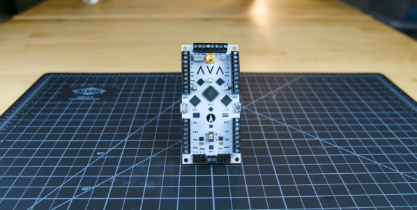
When you’re building and launching a variety of advanced model rockets like [Joe Barnard], you don’t want to spend time building (and debugging) specialized flight computers for every rocket configuration. This challenge has led him to create AVA (All Vehicle Avionics), an impressive model rocket flight computer that he intends to use on all his future rockets.

All of [Joe]’s rockets feature active stabilization and guidance, and comprehensive telemetry using a variety of sensors. On the board there are three separate microcontrollers connected over I2C or SPI, each with its own micro USB port. The two smaller microcontrollers are both ATSAMD21s, also used on the Arduino Zero. The first is used for GPS and inertial navigation, and uses data from onboard and external sensors like the two IMUs (one is a backup), GPS and barometer to estimate the rocket’s position, velocity and attitude, The second is for telemetry, and it handles all external communications via a Bluetooth modem or long range 900 Mhz radio. The main processor (MPU) is a NXP MK20DX256 (also used on the Teensy 3.2), which receives data from the other microcontrollers and handles all the real-time operations and control outputs.

AVA’s predecessors

[Joe] gives a very detailed overview on the board, it’s capabilities, and the reasoning behind some of his design choices in the video after the break. Most of the sensors and microcontrollers were selected partly because of his experience with them. All three microcontrollers have Arduino bootloaders, also due to familiarity with the framework. AVA is the 12th in the line of flight computers [Joe] has built, and it is clear that a lot of work and hard-earned experience went into the design. Continue reading “Advanced Model Rocket Flight Computer Reaching For The Stars”

Automated Tools For WiFi Cracking

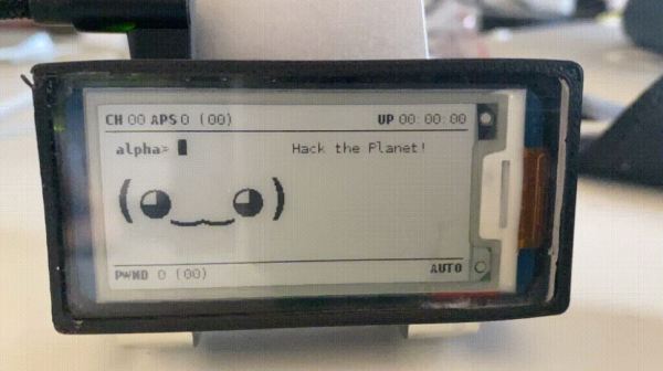
Knowing how WiFi networks can be attacked is a big part of properly securing them, and the best way to learn about it is to (legally) run some attacks. [Matt Agius] has been going down the WiFi-cracking rabbit hole, and in the process created Pwnagotchi Tools to automate the actual password cracking part.

The first step in cracking a WiFi network is to record the handshake that gets exchanged when a client connects to an access point. This has been made very simple thanks to Pwnagotchi, which turns a Raspberry Pi into an automated handshake collection tool and Pwnagothi Tools helps to automate the steps that follow. It downloads the handshakes (pcap files) from the pwnagotchi, and converts it to pmkid/hccapx files to use with the hashcat password recovery tool. Hashcat scripts can then be generated for the actual cracking using any of the attacks that [Matt] has compiled. WPA/WPA2 is slow to crack and requires a lot of processing power, so [Matt] also added the option to automatically provision AWS GPU instances to run the cracking task in the cloud. It also keeps track of the status of each of the handshakes being cracked.

As wireless networks and IoT devices become more pervasive, it’s important to know the dangers, and how to protect against them. WiFi and Bluetooth security is probably the easiest to learn about, but other networks are just as vulnerable when an RTL-SDR is used. Another option Flipper Zero, a hacking gadget for Sub-1 GHz networks inspired by Pwnagotchi, which recently hit $4.8 million in its Kickstarter campaign.

The Ultimate Model Rocket Launchpad

When you’re building advanced rockets as BPS.Space are, an unreliable launchpad is the something you really don’t want to be struggling with. [Joe Barnard] is working on a model rocket that can land vertically under its own power, like the Falcon 9, and has upgraded his launchpad in the process. A lot of thought and hard-earned experience has gone into its design, and the video after the break is a fascinating look the engineering process.

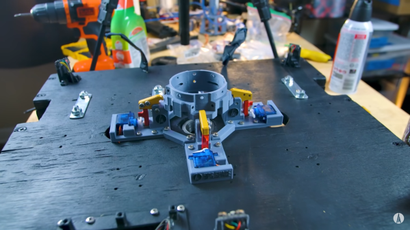
[Joe]’s rockets don’t use guide rods and fins for stabilization in the way most amateur rockets do, but instead have thrust vectoring motor mounts and reaction wheels for active stabilization during launch and flight. The rockets are clamped to the launchpad right up to ignition, and then need to release quickly and reliably. His previous clamps looked very cool, but suffered from high friction forces during release, and the integrated covers prevented easy inspection. These were replaced by much simpler spring-loaded clamp held in place by a small locking bar, which is knocked out by a servo to release the clamp. It also has no static friction, since it moves up and away from the clamping surfaces on the rocket.

The launch pad also features a ATSAMD21 based launch computer named Impulse, which at the most basic level controls the igniter, clamps, buzzer and indicator lights. It also has a number of inputs and outputs to allow for expansion. [Joe] experienced a number of inexplicable failures of rocketry electronics in the past, but believes he has finally tracked down the culprit: Tennessee humidity. He has since started conformal coating all his electronics.

The launchpad itself is made from plywood, so to protect it from the hot exhaust it has in integrated flame trench. This was made from 1 inch steel plumbing components, and directs most of the exhaust out of one side of the platform. It can also be reconfigured to allow a three core rocket like a Falcon Heavy to be launched. Continue reading “The Ultimate Model Rocket Launchpad”