Pokewithastick, An Arduino Programmable Web-logger/server


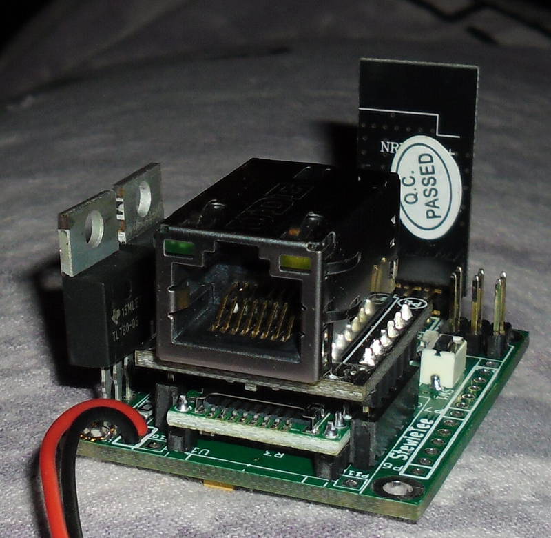
[Stewart] tipped us about his very nice project: pokewithastick. It is an Arduino compatible board (hardware, not footprint) based on the ATMEGA1284P which can be programmed to collect and post data to internet logging sites such as Thingspeak or Xively.

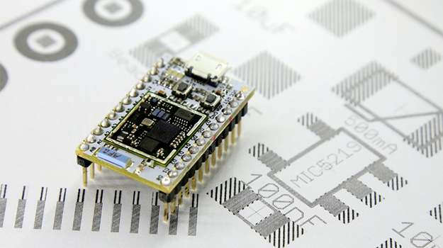
As you can see in the picture above, it has a small 50x37mm footprint (roughly 2″x1.5″). The pokewithastick is composed of an Wiz820 Ethernet module, a micro-SD card slot, 2 serial ports, one battery backed Real Time Clock (RTC), one radio connector (for the usual nRF24L01 2.4GHz radio), one power & user LED and finally a reset button. There are two power rails on the board which can be split (5v + 3.3V) or combined (3.3v only) which may allow you to connect Arduino shields to it. You can program the board using the standard 6-pin header or via a serial programmer if an appropriate (Arduino) bootloader is installed.

The project is open hardware, has been designed using Kicad and all the files can be downloaded as a zip file.

SSTV Beacon Based On A Raspberry Pi

The Budapest hackerspace did some joint work with a local ham radio club and created an SSTV beacon housed inside a CCTV case that takes an image of its environment and transmits it using slow-scan television over ham bands.

As the title says, the build uses a Raspberry Pi to process the image taken from its camera and then transmits it over the air using a Ricofunk UHF transceiver with a main frequency of 433.425MHz. On the software side, PySSTV is used to convert images to frequency/time tuples, UNIXSSTV then creates the actual audio file and finally sox plays it. To avoid screwing up the Raspberry SD card, every part of the filsystem is either mounted in read-only mode (things like /home and /usr) or uses a ramdisk (things like /tmp and logs).

The plans, schematics and source code are available, so they hope that other hackerspaces will join the ranks!

A Laminar Flow Nozzle

A few years ago Hackaday featured a laminar project which recently inspired [Kurt] to create his own. His goal is to create a computer controlled night time light show synchronized with music.

The laminar nozzle shown in the picture above is built with 800 drinking straws all placed in parallel inside a 4″ PVC pipe. The water input is a 3/4″ garden hose adapter, perpendicular to the flow of the output nozzle. The built therefore consists of cleaning sponges placed near the water inlet, followed by the straws and an inch gap to the exit nozzle. To get a nice flow, the edge of the exit nozzle must be as sharp as possible. [Kurt] purchased a brass pipe end cap, drilled a hole in it and sanded it to create a sharp inner edge. For the lights, he used 2 high power LEDs mounted with 3mm fiber optic cables, driven at around 5 Watts.

The link to the article that inspired Kurt can be found here.

Continue reading “A Laminar Flow Nozzle”

Why Kickstarter Projects Are Always Delayed

Most Hackaday readers may remember the Spark Core, an Arduino-compatible, Wi-Fi enabled, cloud-powered development platform. Its Kickstarter campaign funding goal was 10k, but it ended up getting more than half a million. The founder and CEO of Spark [Zach Supalla] recently published an article explaining why Kickstarter projects are always delayed as the Spark core project currently is 7 weeks behind schedule.

[Zach] starts off by mentioning that most founders are optimistic, making them want to embark in this kind of adventure in the first place. In most presentation videos the prototypes shown are usually rougher than they appear, allowing the presenters to skip over the unfinished bits. Moreover, the transition from prototype to “manufacturable product ” also adds unexpected delays. For example, if a product has a plastic casing it is very easy to 3D print the prototype but much harder to setup a plastic injection system. Last, sourcing the components may get tricky as in the case of Spark core the quantities were quite important. Oddly enough, it was very hard for them to get the sparkcore CC3000 Wifi module.

Making A 9GHz Doppler Radar

[Kalle] is currently building an FMCW radar, but as he doesn’t have all the parts finished he decided to build a 9GHZ doppler radar in the mean time. The H-plane horn antennas were made from brass sheet and soldered together. [Kalle] checked the matching between the emitter and the antenna by inserting a directional coupler between the two and measuring the intensity of the reflected signal (approximated return loss). At 9Ghz, the Doppler shift for a 1 meter per second speed is about 30Hz so he connected the radar’s output signal to his soundcard.

A quick explanation of the Doppler effect that a radar uses: if you send an RF signal at a given frequency to a moving target, the reflected signal’s frequency will be shifted. It is commonly heard when a vehicle sounding a siren or horn approaches, passes, and recedes from an observer. The received frequency is higher (compared to the emitted frequency) during the approach, it is identical at the instant of passing by, and it is lower during the recession. Hackaday featured plenty of projects using this effect: a small doppler motion sensor, gesture control using doppler shift, hacking an old radar gun

An Atmega328-based Radioteletype XY Scope Display

[Jack] tipped us about a Crossed Bananas Display (CBD) he just designed. A CBD is a tuning aid for frequency-shift keyed (FSK) modes and is basically an oscilloscope in X-Y mode. At one time, radioteletype operators used binary FSK to transmit text over radio waves. In this scheme, the “1” is called the mark frequency and the “0” is called the space frequency. If both frequencies were perfectly tuned (correct phase) the resulting display would look like the one shown above, explaining the origin of the “crossed banana” name.

The build is based on an ATmega328 and a 1.8″ ST7735R display which has a 128×160 resolution. The MC33204PG operational amplifier is used in conjunction with a potentiometer to scale the input in the microcontroller ADC’s range. Another potentiometer sets the refresh rate of the graph. The whole project is enclosed in a painted cast-aluminium bud box and all the sources for this project can be found here.

A Simple Nixie Clock With Logic Gates

Here is a very nice project that [Znaxque] finished a few months ago: a simple nixie clock made with logic gates only. In this build, the mains 50Hz is used as a time base instead of a 32KHz crystal that most readers here may use. In the very long term, this clock may actually be more precise than a crystal-based one as power companies in Europe adjust the mains frequency. However, at a given moment the difference between this clock and a reference may be as big as 60 seconds.

The design was sketched on a simple piece of paper and later made using salvaged ICs. [Znaxque] only bought the six IN-14 nixies for $45 and the veroboard shown in the picture above. The BCD to Decimal decoders are 74141s and three buttons are present on the board to set minutes, hours, as well as resetting all the counters.