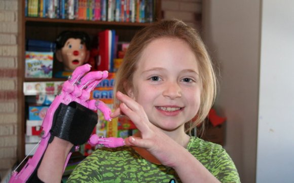
Fubarino Contest: A Shifter With An Easter Egg

shifter

A few months years ago [Wes] shared a project of his on the Hackaday Forums (yes, we do have a forum and you should check it out). He created a shifter for some sim racing, greatly improving on any system that uses a keyboard.

The shifter is made out of some scrap wood, a cutting board cut with an H-gate shape, and a few arcade microswitches. A giant bolt locks into a few cabinet clasps for each gear position, and the set of microswitches connected to a USB game pad tell [Wes’s] virtual car what gear he should be in.

It’s a great build, but because this is an entry for our Fubarino contest, [Wes] needed to put an easter egg with the Hackaday URL in there somewhere. To solve this problem, [Wes] upgraded the electronics with a Teensy 2.0. When the gears are shifted into 1st, 3rd, 3rd, and 7th, the Teensy blinks the URL in Morse and opens up a web browser that loads up Hackaday.

Not only is it a great build, it’s also a very, very subtle easter egg for our favorite website. Demo of the egg below.

Continue reading “Fubarino Contest: A Shifter With An Easter Egg”

Raspberry Pi Wall Calendar

Do you let Google know every aspect of your personal and social life? Do you have a spare LCD monitor kicking around? Why not make your own Raspberry Pi Wall Calendar?

[Alex] recently bought his first home (congratulations!), which happened to have a TV wall mount in the kitchen. Personally, we don’t think TVs belong in the kitchen, and neither did [Alex]. Not wanting to tear the mount out of the wall (and thus require home renovations too soon), he devised a clever solution: why not make a digital calendar?

[Alex] connected a Raspberry Pi model B to the LCD monitor, which provides convenient access to his Google Calendar. His Instructable is both meticulous and approachable, so novice hackers should have no trouble replicating this build. The only improvement we can think to suggest is substituting a touchscreen LCD, which would allow him to interact with the schedule.

Whether you “let” Google know about your life— or it just knows—this is certainly a handy hack for the 21st century home!

Controlling High Voltage 7-Segment Displays

highvoltage7seg

The MAX7219 is one of those parts in your bin that has a “done and done” attitude. In case you’re unfamiliar, this chip can be used to control 7-Segment displays, 8×8 Matrix displays, or even a pile of random LEDs. You talk to it via a simple serial interface and it handles the tasks you don’t want to fuss with, such as multiplexing and modulation. Not all displays are alike, however, so [Raj] wrote in to show how he used the MAX7219 to control high voltage 7-segment displays.

The spec on the MAX7219 only allows an input voltage of 5V, which limits the driver output to around 4V and can cause problems when using large displays that series-connect LEDs internally. [Raj’s] solution allows the MAX7219 to control displays with combined forward voltages of up to 24V, and as an added bonus, the circuit maintains compatibility with existing microcontroller libraries. We imagine this could be a nifty trick to keep on hand the next time you need to control large scoreboard displays.

The circuit works with the help of intermediate drivers to essentially level-shift the voltage to the display, which both provides the high voltage and protects the MAX7219’s inputs. One of the drawbacks of this circuit is losing the MAX7219’s constant current feature, requiring that each segment connection includes a current-limiting resistor. We appreciate this design’s attention to default states, because you wouldn’t want all of your LEDs turning ON during boot-up!

Digital Electric Meter Monitor Goes Old School

powerMeter

[Sal] sent us his digital electric meter monitor, which immediately made us nostalgic for some of Forrest Mims’ books. Sal’s schematic and circuit description are similar to Forrest’s style, and we mean that as a compliment. Even in today’s world of CAD and EDS packages, sketching out a circuit by hand is sometimes both easier and faster. The schematic isn’t the only classic aspect of [Sal’s] design. He’s collecting data using a parallel port on an unused PC: in this case, a Toshiba Libretto running Windows 95. Before cheap flash-based microcontrollers and dev boards were available, the PC parallel port was the go-to hardware hacking interface for many of us. Plenty of the software running those old hacks was written in basic, and [Sal’s] meter is no exception. His software runs on Microsoft QBasic, which shipped with Windows 95.

The circuit takes advantage of the digital meter’s output: a 10 ms pulse for every 1 Wh of energy used. An IR photo detector from RadioShack detects the meter pulses, which are amplified by an LM324 Op Amp. An NPN transistor then shifts the output to send it to two 74LS73 JK flip flops. The first flip flop uses a transistor to drive an LED for visual output. The second JK flip flop sends the data to the PC. The flip flop has the effect of dividing the number of meter pulses by two, creating a much longer toggled signal that a PC can better detect.

Although using an AVR or PIC would consume less power, [Sal’s] setup has already more than paid for its power usage. By monitoring and adapting his electrical usage, [Sal] is saving $20 a month on his electric bill. We’ve included [Sal’s] circuit diagram and source code after the break (apologies to our readers on RSS).

Continue reading “Digital Electric Meter Monitor Goes Old School”

Reverse Engineering An LCD Display

ipod

The current marketplace allows hobbyists to easily find inexpensive, well-documented displays, but what if you wanted to interface with something more complicated, such as the screen on an iPod Nano 6? [Mike] has given us a detailed and insightful video showing his process for reverse engineering a device with little-to-no documentation. Here he covers the initial investigation, where one scours the web in search of any available information. In [Mike’s] example, the display uses an MIPI D-PHY interface, which he has never worked with. He learns that the MIPI Alliance will provide design specs in exchange for a signed NDA (Non-Disclosure Agreement) and a modest $8000 fee. Nice.

[Mike] shows off some serious hardware hackery, tackling some extremely difficult soldering in order to set up a proper test platform. He then demonstrates how to use a rather awesome oscilloscope to better understand the display protocol. We found it fascinating to see the video signals displayed as waveforms, especially when he shows how it is possible to count the individual binary values. The amount of information he uncovers with the oscilloscope is nothing short of amazing, proving these little devices are more complex than they seem.

[via Hacked Gadgets]

Continue reading “Reverse Engineering An LCD Display”

Building Mosaic LEGO Lamps

Looking for a throw back to your childhood, or maybe you just appreciate things that light up and look amazing? Well, [Baron] has a really impressive project for you. Not only does it look stunning and incorporate all of the things we love, it’s actually a pretty novel design. These lamps are built completely out of LEGO Technic pieces, the brand of LEGO that have holes drilled through them so you can build more advanced creations.

[Baron] used these parts with the drilled holes to create a dot matrix in which he placed colored transparent LEGO dots in the holes. The method of creating patterns is very similar to the way it’s done on the “Lite-Brite”. We especially love the theme of these lamps and they would match well with your LEGO mystery box. What’s really great about this tutorial is that it lays down the foundation for LEGO-built lamps that could be more interactive, involve more control (like RGB LEDs), or even introduce some LEGO mechanics!

Testing Six Hundred Fish

fish

That’s the best and most obtuse title you’ll ever see for a Hackaday post, but surprisingly it’s pretty accurate. [Bob] over at the Sector67 hackerspace took part in a 111-day accelerator program in Shenzhen last year to improve his manufacturing skills. He’s just about ready to release his first product, a Bluetooth device that connects to an ice fishing tip-up. The blog for the device recounts the challenges of taking a project from a circuit to a finished product, and illustrates the difference between building something with an Arduino and selling thousands of devices.

The circuit boards for BlueTipz come in panels of eight, but what’s the best way to populate and solder five thousand devices in a reasonably short amount of time? [Bob] hired a few students from the local college to help him out in assembling all these devices. The plastic enclosures were made at a local plastics manufacturer, but the molds were made in China. The manufacturer needed to modify the molds a bit, but after a few days, [Bob] had five thousand enclosures ready to stuff full of electronics.

With the devices assembled, it’s time for programming, and that means building a programmer. [Bob] put all the guts for the device into a plastic box and 3D-printed a mount for the bare BlueTipz board. Put a board on the mount, press a button, and the tech now has a functioning device in his hands.

Besides manufacturing, there’s also a whole lot of testing that went into the design of BlueTipz. Because this is a device for ice fishing—a cold and potentially windy operating environment—[Bob] built a test rig in a freezer. The test rig triggers the device’s sensor, waits two minutes (the amount of time it would take for an ice fisherman to check the tip-up) and resets. They claim the battery life is good for 600 fish, and with this testing rig they were able to verify their calculated battery life with real-world data: without actually catching six hundred fish, of course.

Not only does [Bob] have a good bit of product development under his belt, he was also kind enough to go over the stuff everyday electronic design just doesn’t cover. Developing a product is something you can only learn by doing, and we’re glad [Bob] chose to share his experiences with us.