Autonomous Lighting With Intelligence

myra_light_01_29

Getting into home automation usually starts with lighting, like hacking your lights to automatically turn on when motion is detected, timer controls, or even tying everything into an app on your smart phone. [Ken] took things to a completely different level, by giving his lighting intelligence.

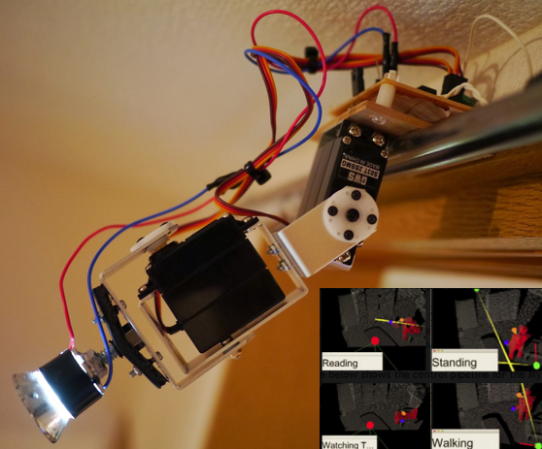
The system is called ‘Myra’, and it works by detecting what you’re doing in the room, and based on this, robotic lights will optimally adjust to the activity. For example, if you’re walking through the room, the system will attempt to illuminate your path as you walk. Other activities are detected as well, like reading a book, watching TV, or just standing still.

At the heart of the ‘Myra’ system is an RGBD Sensor (Microsoft Kinect/Asus Xtion). The space in the room is processed by a PC running an application to determine the current ‘activity’. Wireless robotic lights are strategically placed around the room; each with a 2-servo system and standalone Arduino. The PC sends out commands to each light with an angle for the two axis and the intensity of the light. The lights receive this command wirelessly via a 315MHz receiver, and the Arduino then ‘aims’ the beam according to the command.

This isn’t the first time we’ve seen [Ken’s] work; a couple of years ago we saw his extremely unique ‘real life’ weather display.  The ‘Myra’ system is still a work in progress, so we can’t wait to see how it all ends up.  Be sure to check out the video after the break for a demo of the system.

Continue reading “Autonomous Lighting With Intelligence”

Satisfying Way To ‘Build’ Projects

build button 01_27

When you’re writing code for your next big creation, chances are that you build/debug the project 100’s of times a day. Sure, the keyboard hotkey gets the job done, but is it really that satisfying? [Victor] sends in this quick project on turning an Emergency Stop Push button into a ‘Build’ button.

From the looks of it, this project uses a Teensy 2.0, which sports an ATMEGA32U4. Since this part features a USB controller, it is a piece of cake to get it to mimic a keyboard. The circuit is also very simple; the pushbutton contacts are wired from ground to a digital input. On detection of a ‘press’, the Teensy will send out the keyboard combination to build your project: Ctrl-B, F7, etc… If you prefer working within the Arduino IDE, this could upload sketches as well (Ctrl-U).

Adding a little fun to ‘building’ your projects does come at a cost though. Besides forfeiting a Teensy, you also have to give up a precious USB port. [Victor] does mention Bluetooth, but that could break your budget for this sort of project. A possible alternative to the Teensy could be to implement Virtual USB on a low-cost standalone Arduino.

Continue reading “Satisfying Way To ‘Build’ Projects”

Electric Imp Thermal Printer

imp_printer_01_23

If you’re the type of person that doesn’t mind having a pocket/purse full of crumpled receipts, then maybe you should check out this tutorial from [tombrew] on giving a thermal printer internet-connectivity.

For some of us, there’s something kind of cool about thermal printers, but it’s probably not the kind of project you’d want to burn a lot of calories on. As a developer over at Electric Imp, [tombrew] agrees with this statement, but since the Electric Imp contains both a WiFi module and processor built in, it makes it pretty easy to get your thermal printer printing off the daily weather, stock prices, news headlines, etc… In fact, the claim here is that you could have this project completed before you even finish your morning coffee… knock on wood!

From a hardware standpoint, the project is pretty straight forward; an Electric Imp with breakout board, thermal printer, and a power supply are pretty much all that’s needed. Local communication between the Electric Imp and the thermal printer is accomplished through a simple serial interface. With the roll-out of the new Electric Imp IDE a few months back, we were introduced to ‘Agents’. This is kind of a neat concept, and this tutorial breaks everything down, but basically the agent is server-side code that runs in the ‘ImpCloud’, thus giving your Electric Imp more power and capabilities to deal with complex APIs. Also, handling images (like something you want to print) can take up a ton of memory, so for this project, the agent is used to send down slices of the image you want to print one at a time. This project is just the beginning of what [tombrew] has planned, so we can’t wait to see more insanely detailed tutorials.

CFL + Bugzapper = Battery Operated Camping Light

CFLBugzapper_01_20

Knowing different ways of generating light is a great skill to have, so go ahead and add this one to your arsenal by combining a Bugzapper with a CFL Light Bulb.

Sure a CFL(Compact Fluorescent Lamp) works just fine on its own if you have AC mains, but what we’re talking about here is getting the light bulb to work off of a single D battery. We featured a similar hack a few months back by using a Joule-Thief to get the high voltage for the fluorescent tube, but if you can’t get your hands on discrete components, [Jan] shows us another way by gutting a tennis racket bugzapper for its booster board. Knowing that the bugzapper steps up the 3V to about 2000V, he decided to see if that same circuit would run off a single 1.5V D battery and achieve the voltage required to drive a CFL tube. After carefully removing the electronics from the CFL housing, [Jan] was able to directly connect the booster board to the electrode wires of the fluorescent tube, and voila; he now has a D-Battery operated camp light that has a run time of over 200 hours.

It would be interesting to see how this hack compares to the Joule-Thief method in terms of brightness and run-time. Before you go and scrap the parts out of the CFL light bulb, make sure you check out this detailed breakdown of popular CFL light bulbs.

USB Datalogging With Arduino Using V-USB

Adding USB functionality to your Arduino projects used to be a pain, but thankfully, the V-USB project came along and gave your ATMEGA328 the ability to control the USB lines directly and mimic simple (low-speed) USB peripherals. [Ray] shows an implementation of the V-USB project by logging the status of the Arduino’s I/O pins to an open Excel spreadsheet

V-USB (Virtual USB) is especially useful for those of us who build standalone Arduino projects with the ATMEGA328. Unlike the Arduino Leonardo and its ATMEGA32U4, the ATMEGA328 does not have a built-in USB controller. The circuit required to tie into the USB lines is made up of just a few basic components, and [Ray] provides a reference schematic and BOM to get you started. The Arduino is programmed to mimic a keyboard, so the datalogging is achieved by allowing the Arduino to ‘type’ the data into an open Excel spreadsheet. In this example, the status of 8 digital pins and all 6 Analog Input pins are logged.

For those of you who prefer the PIC microcontroller and are in a similar position of not having a built-in USB controller, there is the 16FUSB project to help you out.

Android+Arduino – Face Following RC Car

androidRCcar_01_14

To some of us, hacking an RC Car to simply follow a black line or avoid obstacles is too easy, and we’re sure [Shazin] would agree with that, since he created an RC Car that follows your face!

The first step to this project was to take control of the RC Car, but instead of hijacking the transmitter, [Shazin] decided to control the car directly. This isn’t any high-end RC Car though, so forget about PWM control. Instead, a single IC (RX-2) was found to handle both the RF Receiver and H-Bridges. After a bit of probing, the 4 control lines (forward/back and left/right) were identified and connected to an Arduino.

[Shazin] paired the Arduino with a USB Host Shield and connected it up with his Android phone through the ADB (Android Debug Bridge). He then made some modifications to the OpenCV Android Face Detection app to send commands to the Arduino based on ‘where’ the Face is detected; if the face is in the right half of the screen, turn right, if not, turn left and go forward.

This is a really interesting project with a lot of potential; we’re just hoping [Shazin] doesn’t have any evil plans for this device like strapping it to a Tank Drone that locks on to targets!

Continue reading “Android+Arduino – Face Following RC Car”

504 Segment Clock

FIveOfour_01_13

Trying to reinvent the clock has been done over and over again, but it’s always fun to see how over-engineered and complex these designs can get. [Bertho’s] last working clock in his house was the built-in clock on the VCR, so he decided it was finally time to build his own 504 Segment clock.

Yep, that’s right, 504 Segments! This clock uses 72 7-Segment displays to tell time. The video after the break shows the clock in action, but time is read by looking at each ring of displays: outer=seconds, middle=minutes, and inner=hour. [Bertho] could’ve just stopped there, but he decided to load the display up with sensors, so hand-waiving can change modes, and brightness can be regulated based on ambient light conditions. And since he has individual control over each segment, he has implemented some pretty cool mind-melting animations. Oh, and did we mention that the display synchronizes with an NTP server?

The display is divided into 4 quadrants, each containing 18 7-Segment displays. The control architecture is interesting because each quadrant is controlled by its own PIC microcontroller, which handles the continuous multiplexing and modulation of the 18 7-Segment displays.  A main control board contains another (more powerful) PIC to update the 4 quadrants via a serial bus. This board also handles the Ethernet connection, sensor interface, and local RTC(real time clock). This isn’t the first time we’ve seen [Bertho’s] amazing work, so make sure you check out his useless machine and executive decision maker.

Continue reading “504 Segment Clock”