CheerLights: Synchronizing Christmas Lights Around The Globe

cheerlights-synchronized-christmas-lights

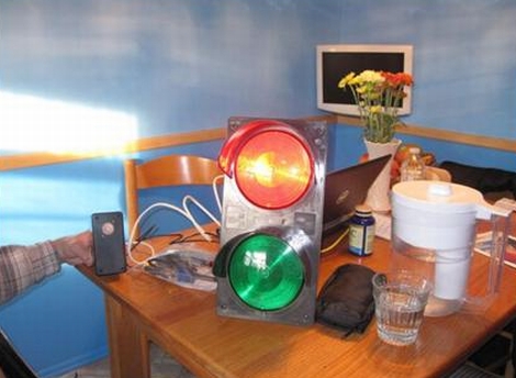
They say that the holidays are a time to gather with others, which usually translates into spending time with friends and family. The folks at ioBridge Labs thought that while friends and family certainly are a big part of the holidays, it would be pretty cool to gather together flocks of strangers by using the Internet to synchronize their Christmas lights.

Participation in CheerLights is pretty easy, requiring little more than an Internet connection, some GE G-35 Color Effects lights, an Arduino, and an ioBridge. While those are the recommended components, an Arduino Ethernet shield will handle networking just as well. There really are no restrictions when it comes to hardware, so if you are so inclined, it should be relatively easy to roll your own display using simple RGB LEDs and a µC of your choosing.

The colors are dictated by the group’s Twitter feed, which can be found at http://twitter.com/#!/@cheerlights. Whenever a message is sent to @cheerlights along with a color, all of the light displays listening in will change simultaneously.

We really like the idea, and think it would be pretty cool to see this sort of program rolled out on a neighborhood or street-wide level, so you could see dozens of strings changing colors all at once.

If you’re interested in checking out CheerLights’ current color, be sure to take a gander at their live stream here.

[via BuildLounge]

Data Logging With A Cheap Lux Meter

[Minisystem] has a thing for dynamo powered bike lights. He wanted to measure how well his latest is working, but just logging the current flow through the LEDs wasn’t enough for him. He picked up a cheap Lux meter and hacked into the circuit to log measurements while he rides.

He started by cracking open the case to see what the meter held inside. There’s a Texas Instruments Op-Amp that connects to the light sensor. The datasheet for the part didn’t help much, but [Minisystem] did find that the current output on one of the pins changes with light intensity. Further testing led him to discover that the signal is a multiple of 10 for what is shown on the Lux meter’s readout. All he needs to do is take regular measurement of this current and save that data.

To do this, he grabbed his trusty Arduino and made a connection between one of its analog inputs and the op-amp pin. It should be easy enough to dump measurements into the Arduino’s own EEPROM, or use an external storage chip or SD card.

[Thanks Jason]

Censoring All The ‘F’ Words On TV

[Milton] sent in a build that censors every ‘F’ word on TV, and not just the one that rhymes with ‘duck,’ either. His setup sounds the alarm every time someone inside the moving picture box says a word that contains the letter F.

The build is based around Nootropic Design’s Video Experimenter Shield. This neat little shield has been used as a video sampler and has analyzed what the talking heads are actually saying. The Video Experimenter Shield has support for closed captions, meaning a transcript from a TV show can be read in real-time. All [Milton] had to do so the ‘F word’ alarm could be sounded was strchr().

The F-Chip, as [Milton] calls his build, includes three outputs – a solenoid sounds a bicycle horn, sends some air through a whistle, and lights up an ‘F-word’ alarm. From the video of the F-Chip in action (available after the break), we can tell that this build is awesome, thoughtful, and annoying. The only way it could be made more annoying is by making an ‘E-word’ alarm, but there are ways around that.

Continue reading “Censoring All The ‘F’ Words On TV”

Ultrasonic Combo Lock

[John Boxall] took a different route for a single-input combination lock. This unit uses a Ping ultrasonic range finder to input a four digit code. It’s a hardware upgrade, but uses the same basic concept as his button-based combo lock. That design used an Arduino to measure how long you hold down a single button, with a one second pause between inputs, to enter the code. This one also uses timing to establish when each digit is read, but that digit is grabbed as the distance between your hand and the sensor.

There are things we like and dislike about the redesign. This is obviously much more expensive than other button-based locks like this garage door opener we built. If we were to run with [John’s] design, we might spring for the Ping sensor (because it’s a pretty cool input) and replace he character LCD with an LED or two. The other drawback that we see here is that it may be easy for someone to steal your code by watching from afar. Still, we love the project and think you will too after seeing the demo clip below.

Continue reading “Ultrasonic Combo Lock”

Music-synced Christmas Light Suit

Ah, the end of the 4th financial quarter – the magical time of increased sales, being at work the entire time the sun is up, and holiday parties. For [Andy] at National Instruments, though, things don’t seem too bad. He built a neat Christmas light suit to entertain everyone with his brilliant persona.

[Andy] always loves great Christmas light displays (he even blogs about them), so he figured a wearable light display synchronized with music would be very doable. The build is controlled with LabVIEW to convert .WAV files to power levels and frequency bands. This info is then piped into the Arduino that controls the lights.

[Andy] actually made two light suits, one for him and one for his friend [Richard]. Both guys have two light-up Christmas staffs to wield light mage powers on their coworkers. The lighsuits are controlled by Arduino/Xbee setups – one each for each suit and staff. The result is phenomenal, and should really get everyone in the holiday spirit.

Chrono-tomic Shield Helps Your Arduino Keep Perfect Time

chronotomic-arduino-shield

[Josh] and his lab partner [Eric] needed a final project for their Embedded Systems Design class, and thought that designing an Arduino shield would be a cool idea. They noticed that there are plenty of ways to get an Arduino to keep time, though none that they knew of utilized WWVB (Atomic Time) signals directly.

The Chrono-tomic Arduino shield uses a C-MAX radio to demodulate the WWVB signal, demodulating it and passing it along to a PIC16F1824 microcontroller. The PIC decodes the data frame and verifies it is valid, sending the time to an MCP79410N real-time clock module.

We can hear the “Yo dawg I herd you like microcontrollers so I put a microcontroller on your microcontroller shield” jokes already, but the pair says that they offloaded the time processing to the PIC in order to let the Arduino focus on whatever tasks it has been delegated. The Arduino code merely needs to request the time from the RTC whenever it is required, rather than deal with the decoding itself.

Is it overkill? Perhaps – though we think it heavily depends on your application and configuration. We can certainly conjure up situations where it would be useful.

arduino-seismic-sensor

Detecting Seismic Waves With A Piezo Element

While we normally see piezo elements being used to output audio, [Veedo] thought that they could be used in a more useful manner. He bought way too many piezo film tabs and decided to use them to build a makeshift seismic sensor.

The piezo tabs came with weights attached at one end, though while testing them, he found that they more or less only detected vibrations with frequencies in the KHz range. Since earthquakes tend to produce vibrations in the 30-80 Hz range, he had to tweak his setup to detect the proper frequencies. To do this, he attached a weight made of a screw and washers, checking the output signals on his oscilloscope until the dominant sensed frequencies were in the range of 40 Hz.

The sensor was attached to a breadboard, then wired through a charge amp to create a small AC signal, which floats on 2.5Vdc. The bottom half of the wave is chopped off with a diode, after which it is fed into an Arduino Mega. The seismic data is then pushed up to his Pachube account for storage, though he can view the feeds locally via the a web server programmed into the Arduino.

We’re not sure how much advanced notice this sort of setup would give you in the event of an earthquake, but it seems like a fun project to build either way.