Arduino Notebook Cover Makes It Easy To Tinker Anywhere

arduino-notebook-cover

[Erv] was putting his holiday shopping list together and decided that instead of buying his friends something from the store, he would give them something a bit more useful. A former Electrical Engineer by trade, [Erv] typically prefers PIC microcontrollers, but he says that Arduinos are just so convenient to use for prototyping that he likes to always have one on hand.

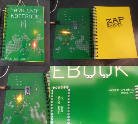
He figured that his friends might enjoy having easy access to an Arduino as well, so he made them some slick ZapBook covers which enable them to have a prototyping platform on hand at all times. The cover is made from a PCB and includes a socket for an Arduino Pro Mini, along with a handful of built-in LEDs. He has extended a few other I/O pins from the Arduino as well, but he says that the small solder bridges connecting the LEDs can be removed in a pinch, freeing up 8 additional pins with ease. We are pretty keen on the idea of an easily portable prototyping setup, though it doesn’t hurt that [Erv] incorporated a Hack a Day skull with light up eyes into his design either!

We’re not sure if he’s planning on releasing the schematics for the board, but the notebooks would be pretty useful for any hackerspaces hosting beginner Arduino programming classes.

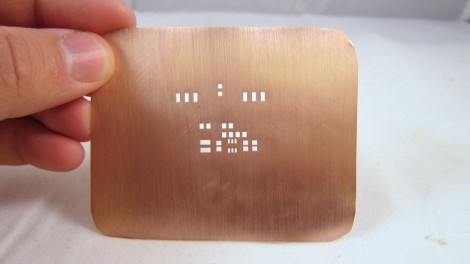
How To Etch Your Own Solder Paste Stencils

We’re kind of surprised we haven’t covered this concept before since it only uses techniques that are commonly avaialable for home PCB fabrication. [Ray] made this solder paste stencil out of a sheet of copper using the same etching techniques you would for a circuit board. He designed and printed a resist pattern, with toner everywhere except the places where there should be holes in the stencil. He transferred the toner to the copper using an iron.

The difference here should be obvious; this a thin copper sheet with no substrate. Because of that, you must protect the copper surface before etching. he covered the entire thing, both sides, in packing tape. After that it’s into the Cupric Chloride bath to dissolve the exposed parts. Once the tape and toner has been removed you can scree a precise amount of solder paste onto your boards.

This isn’t for everyone, but if you’re assembling many boards it’s not a bad approach. If the stencil is no longer used it can be recycled, but we do wonder how corrosion on the copper will affect the stencil’s performance.

The idea for this technique came to [Ray] from a guide that’s been around for years.

Scratch-built Software-Defined Radio

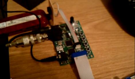
[Ben] is showing off some results from his Software-Define Radio project. The board seen above, which he designed from the ground up, is receiving a WWV radio broadcast. This is the atomic clock signal from Fort Collins, Colorado. The audio heard in the clip after the break is a bit noisy, but since he’s about 2000 miles from the origin of the signal we think he’s done really well!

The seed for this build was planted in [Ben’s] head back in July when he saw [Jeri Ellsworth’s] SDR project. He’s posted some of the build details up in a forum post. The approach is similar to [Jeri’s] but there are several key differences. He’s using a DS1085 programmable oscillator where she chose an FPGA for that purpose. Once his hardware demodulates and filters the incoming signal, a PIC32 does the rest of the work and outputs a PWM signal to an Op-Amp to generate audio.

Continue reading “Scratch-built Software-Defined Radio”

Flowerboard LED Cube

Here’s a neat 4x4x4 LED cube made with an ElecFreaks Flower Protoboard.

A few days ago, we posted a neat new prototyping board made specifically for SMD work. Instead of the usual ‘holes-with-circles’ protoboard layout, the ElecFreaks team decided to go with a flower-shaped pad. This makes it especially easy to deal with SMD components when building whatever. To demonstrate their new protoboard, ElecFreaks built an awesome-looking 4^3 LED cube. Just look at those solder traces.

The LED cube itself is nothing we haven’t seen before, but the construction of this thing is amazing. The entire build is on the Arduino Mega Flower shield, meaning there are no wires at all. Everything, from the resistors to the transistors, is an SMD component. The only problem now is bending and soldering all those LED leads.

This Flower Protoboard is starting to look more and more interesting; check it out in action after the break.

Continue reading “Flowerboard LED Cube”

EFF On Securing Digital Information When Crossing The Border

The Electronic Frontier Foundation, long-time defenders of the common man’s rights in the electronic realm, has published a guide to keeping your digital devices private when entering the United States. It seems the defenders of freedom and liberty (ICE, DHS, TSA, and CBP) are able to take a few freedoms with your liberty at a border crossing by seizing your devices and copies of the data they store for up to five days. This requires no suspicion of wrongdoing, and copies of this data may be shared with other agencies thereby negating the five day limit.

Do you have a reason to protect your digital property? This is discussed in the paper. It may be confidential information, by way of a business contract or professional relationship (Doctors, Lawyers, Journalists, etc.). Or you may just want to keep your privacy on principle. No matter what your stance, the EFF has covered all the bases in this intriguing read. We think the best advice they give is to make an encrypted backup of your data on the internet, blank your computer before the border crossing, and restore it when you get to your destination. If you don’t have the data with you, it can’t be compromised. It that’s not an option, they have plenty of guidelines on cryptographic techniques.

Continue reading “EFF On Securing Digital Information When Crossing The Border”

Reverse Engineering The Icebreaker POV Toy

[Ch00f] spent some serious time figuring out how the Icebreaker POV toy works. This is a pretty cool device about the size of a toothbrush holder. It’s in a clear plastic case, which lets the row of 32 surface mount LEDs shine through. But making light isn’t their only function. You can use the device to scan in a high-contrast design, then ‘play it back’ using the persistence of vision display properties of the LED strip.

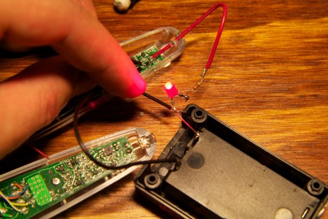
Perhaps the biggest question on [Ch00f’s] mind was how the sensing is done. He made a series of observations, then started monkeying around with the LEDs to investigate them. It seems that one LED is lit up while the ones around it are used as light sensors. This becomes more confusing once he realized that the display was multiplexed.

His write-up includes a collection of schematics that can be pieced together to conceptualize the entire circuit. The image above was taken during this process, using an LED to check the connections on a part. This let him prove that it’s an N-channel MOSFET. He plans to take what learned and roll it into his own project.

[via Reddit]

Numitron Tube Tutorial

Nixies and VFDs are great displays, but when using them you’ve got to deal with some fairly high voltages, at least for the micro projects we see on Hack a Day. Luckily, there’s another ancient technology that can be driven at tiny voltages. [Kenneth] put up a great tutorial on Numitron tubes to show the Internet how to get these guys working.

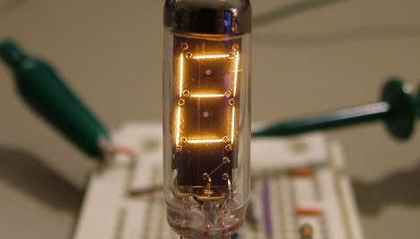
Numitron tubes are like Nixies, but instead of the ten number-shaped filaments in each Nixie, Numitrons are old-school seven-segment displays. [Kenneth] picked up a few on ebay and the seller was kind enough to include a Russian data sheet. Each filament in his IV-9 Numitrons required about 20mA to light up, perfect for the constant current LED drivers [Kenneth] picked up

The test circuit consisted of an ATtiny2313 and an A6278 LED driver. The code on the ATtiny cycles the digits 0 through 9. This is sent through the LED driver and lights up the tiny filaments inside the tube. Check out the video after the break to see the Numitron in action

Continue reading “Numitron Tube Tutorial”