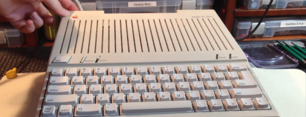
The Vectrex is a rare beast in the world of retro video games. Introduced in 1982, this was the only video game system to put a monitor right in the console, and it did so for good reason. This was a games system with vector graphics and rotating 3D objects, something that just couldn’t happen on the TV in the family room. A while ago, [John] dug his old Vectrex out of his basement and replaced a faulty logic board. The CRT was still broken, but with a little bit of research and a not-so-ugly kludge, he managed to replace the CRT in a Vectrex.
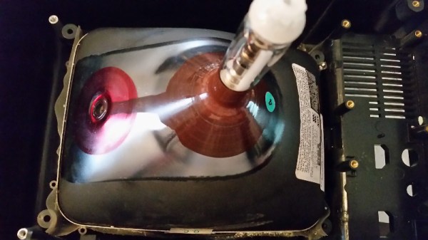
[John] found someone willing to part with an old CRT online, and after whipping out his credit card, the tube was on his way to his front door. This new tube wasn’t a direct drop in; The original Vectrex had small ears around the edges of the screen that served as mounting points. The new tube had no such ears. Now, a bit of plastic strapping holds the CRT in the chassis. It’s a bit of a kludge, but at least now [John] has a source of Vectrex CRTs.
While the rest of [John]’s repair work didn’t go as well – the Vectrex in question still has all the logic board problems it had when it was taken out of storage. This Vectrex does have a new CRT, and with a bit more work on rehabbing this old machine, it should keep on working for another thirty years.
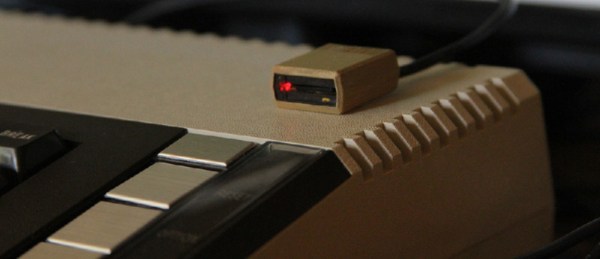
Whenever you come cross an interesting CRT, make sure you snatch it up. Here’s another offering that uses a tiny screen for some classic MAME action.