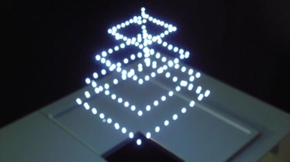
There’s a new display technique that’s making the blog rounds, and like anything that seems like its torn from [George Lucas]’ cutting room floor, it’s getting a lot of attention. It’s a device that can display voxels in midair, forming low-resolution three-dimensional patterns without any screen, any fog machine, or any reflective medium. It’s really the closest thing to the projectors in a holodeck we’ve seen yet, leading a few people to ask how it’s done.
This isn’t the first time we’ve seen something like this. A few years ago. a similar 3D display technology was demonstrated that used a green laser to display tens of thousands of voxels in a display medium. The same company used this technology to draw white voxels in air, without a smoke machine or anything else for the laser beam to reflect off of. We couldn’t grasp how this worked at the time, but with a little bit of research we can find the relevant documentation.
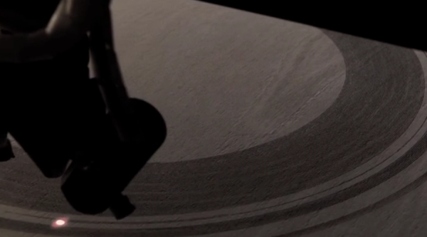
A system like this was first published in 2006, built upon earlier work that only displayed pixels on a 2D plane. The device worked by taking an infrared Nd:YAG laser, and focusing the beam to an extremely small point. At that point, the atmosphere heats up enough to turn into plasma and turns into a bright, if temporary, point of light. With the laser pulsing several hundred times a second, a picture can be built up with these small plasma bursts.
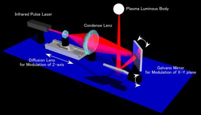
Moving a ball of plasma around in 2D space is rather easy; all you need are a few mirrors. To get a third dimension to projected 3D images, a lens mounted on a linear rail moves back and forth changing the focal length of the optics setup. It’s an extremely impressive optical setup, but simple enough to get the jist of.
Having a device that projects images with balls of plasma leads to another question: how safe is this thing? There’s no mention of how powerful the laser used in this device is, but in every picture of this projector, people are wearing goggles. In the videos – one is available below – there is something that is obviously missing once you notice it: sound. This projector is creating tiny balls of expanding air hundreds of times per second. We don’t know what it sounds like – or if you can hear it at all – but a constant buzz would limit its application as an advertising medium.
As with any state-of-the-art project where we kinda know how it works, there’s a good chance someone with experience in optics could put something like this together. A normal green laser pointer in a water medium would be much safer than an IR YAG laser, but other than that the door is wide open for a replication of this project.
Thanks [Sean] for sending this in.
Continue reading “How A Real 3D Display Works” →