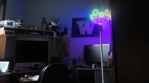
[burgerga] loves attending Music Festivals. He’s also a MechE who loves his LED’s. He figured he needed to put it all together and do something insane, so he build a huge, 15″ geodesic sphere containing 540 WS2812B addressable LED’s. He calls it the SOL CRUSHER. It sips 150W when all LED’s are at full intensity, making it very, very, bright.
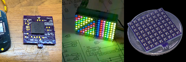
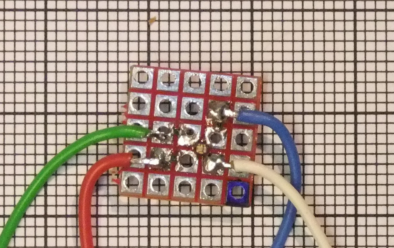
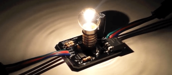
As with most WS2812B based projects, this one too is fairly straightforward, electrically. It’s controlled by four Teensy 3.2 boards mounted on Octo WS2811 adapter boards. Four 10,000 mAh 22.2V LiPo batteries provide power, which is routed through a 5V, 30Amp heatsinked DC-DC converter. To protect his LiPo batteries from over discharge, he built four voltage monitoring modules. Each had a TC54 voltage detector and an N-channel MOSFET which switches off the LiPo before its voltage dips below 3V. He bundled in a fuse and an indicator, and put each one in a neat 3D printed enclosure.
The mechanical design is pretty polished. Each of the 180 basic modules is a triangular PCB with three WS2812B’s, filter capacitors, and heavy copper pours for power connections. The PCB’s are assembled in panels of six and five units each, which are then put together in two hemispheres to form the whole sphere. His first round of six prototypes set him back as he made a mistake in the LED footprint. But it still let him check out the assembly and power connections. For mechanical support, he designed an internal skeleton that could be 3D printed. There’s a mounting frame for each of the PCB panels and a two piece central sphere. Fibreglass rods connect the central sphere to each of the PCB panels. This lets the whole assembly be split in to two halves easily.
It took him over six months and lots of cash to complete the project. But the assembly is all done now and electrically tested. Next up, he’s working on software to add animations. He’s received suggestions to add sensors such as microphones and accelerometers via comments on Reddit. If you’d like to help him by contributing animation suggestions, he’s setup a Readme document on Dropbox, and a Submission form. Checkout the SolCrusher website for more information.
Thanks [Vinny Cordeiro], for letting us know about this build.
Continue reading “540 LEDs On A Geodesic Sphere” →