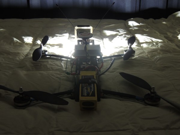
Touching Conversations: Email Snippets Scroll By On Electro-Embroidery Piece

electroembroidery

[Wei Chieh Shih] really moves the needle when it comes to wearable technology. His textile design project entitled I Am Very Happy I Hope You Are Too is a striking marriage of masterful hand embroidery, delicate circuitry, and careful programming.

[Wei] is using an Arduino micro to drive a matrix of surface-mount LEDs in the Hello, World video, which is a ramp-up to the scrolling text version that’s in progress now finished. That full version is part of his residency project at Arquetopia in Oaxaca, Mexico and displays snippets of emails from his past relationships. It’s huge, with multiple matrices as large as 8×25 pixels!

No build notes could be found for this or any of [Wei]’s similar projects, like this awesomely dangerous 200 laser diode jacket or this eerily beautiful light installation on Taiwan’s north beach. Based on the pictures, our speculation is that he is using ordinary 6-strand embroidery floss to make stem or half cross-stitches on all the paths. He then runs very thin, flexible conductor underneath the channel of stitches and solders the wires to the component pads.

If [Wei] wants another way to wear his heart on his sleeve, he could investigate these dynamic LED clothing hacks.

Update: [Wei] has completed this project, and has more information available at his Behance site.

Continue reading “Touching Conversations: Email Snippets Scroll By On Electro-Embroidery Piece”

Fubarino Contest: Morse Code Christmas Baubles

fubarion-contest-christmas-morse-code

Fubarino Contest entries are starting to roll in at a faster rate. If you’re working on one you only have a few hours left! Submissions are due before 12:00am Pacific Time! This bit of inspiration is a two-fer. Both entries decided to use Morse Code to spell out the Hackaday URL.

First up, [Tariq] is getting into electronic design because his friend’s 8-year-old son [Yago] is really interested in Math and Science. The device he was working on is a little portable Morse Code message flasher (don’t miss part 2). The idea is that [Yago] can carry it around and pretend it’s a spy device containing a secret message. It might as well be since your average Joe probably wouldn’t notice the irregular flashing and if they did they wouldn’t be able to decode it without some help. The device is built around an ATtiny85. Normally it displays a Christmas greeting for [Yago]. But at the end of the cycle, or at power-up, it flashes the Hackaday URL at an extreme rate. Can anyone actually decode this without putting it on a logic analyzer?

The second offering is in the form of a blinky Christmas tree. [Jim] built the Arduino-compatible ornament for the holidays. It does a great job of flashing a bunch of different patterns, and it wasn’t too much work for him to make it flash the URL.


This is an entry in the Fubarino Contest. Submit your entry before 12/19/13 for a chance at one of the 20 Fubarino SD boards which Microchip has put up as prizes!

Arduino Xmas Tree Shield

christmasshield

Nothing reminds us that it’s the holiday season more than an LED Christmas Tree submission. This obviously is not the first of its kind, but [Jose] does offer up a new technique using addressable RGB LEDs.

[Jose] decided to use 20 WS2812B RGB LEDs, which if you haven’t seen before, are RGB LEDs with an integrated controller. Yep, that’s right, just power/ground and 1 data line is all that is needed to control hundreds of RGB LEDs. This LED tree’s design is simple: a custom-etched PCB cut it in to the shape of a Christmas tree. The WS2812B LEDs helped keep everything clean, so the tree lacks any ‘ugly’ ornaments, except for the required bypass cap here and there. For an added bonus, the tree’s LEDs are synchronized to music generated by an Arduino via a piezo buzzer. Why is it a shield?  Well, the whole tree plugs in nicely to a standard Arduino interface. This looks like the perfect starter project to familiarize yourself with addressable LEDs, or at least to get you warmed up before building your own infinity portal.

Continue reading “Arduino Xmas Tree Shield”

Snowden Immortalized As Bond Villain In Edge-Lit Acrylic Poster

snowfall_smaller

[Wilywyrm] needed to come up with a final project for art class that commented on a social issue. Healthcare, schmealthcare, he said, and busted out this movie poster about the NSA spying scandal instead.

The circuit uses three extended-duty astable 555 timers to control the brightness of the 5050 RGB common-anode LED strips that run up the sides of the 24″ x 12″ x 1/4″ acrylic panels. Each of the three panels was laser-engraved at 600 DPI on an Epilog laser engraver and features a different aspect of the poster. There’s one for Snowden, one for Daniel Craig, and one for the text.

[Wilywyrm] tied the color channels together in the first panel to output white light. He used red for the second panel and blue for the third. A complete list of parts with build notes is available on his Google Drive. [Wilywyrm]’s notes include improvement ideas, like making all the RGB strips color-adjustable with more 555s or a microcontroller and timers.

Perhaps [Wilywyrm] could get into the clear whiteboard business after college.

Particle System Busy Box Keeps Baby Occupied

Busybox

Any child born today has a bright future ahead of them—mostly consisting of watching glowing rectangles for 80 or 90 years. To give his progeny a jump-start on a lifetime of watching LEDs flicker, [Dan] created a busy box. It’s really just an Arduino, RGB LED matrix, and a programmed particle system, but if we’re fascinated by it, it will probably blow an infant’s mind.

The idea for this busy box originated with an earlier Hackaday post that used an 8×8 matrix of RGB LEDs to create a moving color cloud. [Dan] took this project as a jumping off point and created an infant’s busy box with four modes that are sure to be entertaining.

Inside the is a Rainboduino: an Arduino compatible board capable of driving an 8×8 RGB LED matrix. Also stuffed inside the busy box is a 9V battery, rocker switch for the power, and four arcade buttons that cycle through each mode. The first mode is some sort of ‘plasma cloud’ simulation, the next is a ‘painter’ light display. The final two modes spell out [Dan]’s spawn’s name, and all the numbers and letters of the alphabet.

Continue reading “Particle System Busy Box Keeps Baby Occupied”

Reverse Engineering A Candle Flicker LED

Candle flicker LEDs are a one part replacement for a real candle. They contain both a yellow LED and a control chip that modulates the light to create a candle effect. [Cpldcpu] took a deep look into reverse engineering one of these LEDs.

To analyze the circuit, which is potted into the LED itself, a shunt sense resistor was connected to the LED. By connecting this resistor to a logic analyzer, the control signal could be observed.

This control signal looked like pulse width modulation, with some randomness to the duty cycle. [Cpldcpu] determined that a linear feedback shift register was most likely used to generate a pseudeorandom bitstream, and some shaping was applied to make the LED look more like a real candle.

It turns out a blinking LED can be quite complex, and this takes a deep look into it by analyzing the signal. [Cpldcpu] took the lessons learned and wrote an implementation of the algorithm for AVR.

Controlling High Voltage 7-Segment Displays

highvoltage7seg

The MAX7219 is one of those parts in your bin that has a “done and done” attitude. In case you’re unfamiliar, this chip can be used to control 7-Segment displays, 8×8 Matrix displays, or even a pile of random LEDs. You talk to it via a simple serial interface and it handles the tasks you don’t want to fuss with, such as multiplexing and modulation. Not all displays are alike, however, so [Raj] wrote in to show how he used the MAX7219 to control high voltage 7-segment displays.

The spec on the MAX7219 only allows an input voltage of 5V, which limits the driver output to around 4V and can cause problems when using large displays that series-connect LEDs internally. [Raj’s] solution allows the MAX7219 to control displays with combined forward voltages of up to 24V, and as an added bonus, the circuit maintains compatibility with existing microcontroller libraries. We imagine this could be a nifty trick to keep on hand the next time you need to control large scoreboard displays.

The circuit works with the help of intermediate drivers to essentially level-shift the voltage to the display, which both provides the high voltage and protects the MAX7219’s inputs. One of the drawbacks of this circuit is losing the MAX7219’s constant current feature, requiring that each segment connection includes a current-limiting resistor. We appreciate this design’s attention to default states, because you wouldn’t want all of your LEDs turning ON during boot-up!