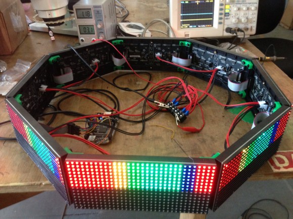
The folks at NYCResistor have a new toy in the Octoscroller. For a couple of years now the NYCResistor crew has used the HexaScroller as a clock and general alert system. Now that RGB LED panels are cheaply available, the group decided to upgrade both the number of sides and the number of colors.
Octoscroller uses eight 16×32 RGB LED panels. These panels are relatively easy to interface to, but require constant refresh even to display a static image. This makes them both memory and CPU intensive for smaller microcontrollers. Brightness control via PWM only increases the difficulty.
On the plus side, the panels are structurally strong. This allows the Octoscroller to avoid the plywood ring which made up the frame of the Hexascroller. 3D printed brackets and hardware were all that was needed to complete the Octoscroller frame.
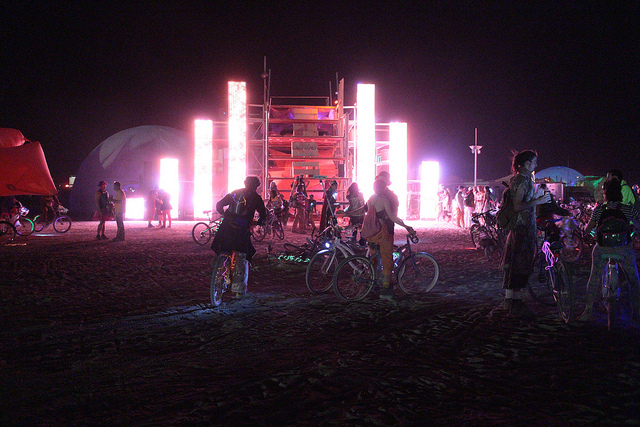
The brain of the this beast is a BeagleBone Black running LEDscape along with some custom software. Imagery comes from the Disorient Pyramid.
If you’re in the New York area, NYCResistor plans to offer classes on building your own Octoscroller. You can also see the Octoscroller in person at MakerFaire NYC this weekend.