Reverse Engineering LED Vodka Bottle Displays

wireless_led_marquee

When [Tyler] heard about the LED matrix display that Medea Vodka was building into their bottles, he immediately wanted to get his hands on one. Who could blame him? Someone had finally combined two things we love dearly: booze and LEDs.

He struggled to find a bottle at any of his local stores for the longest time, but was absolutely stoked when he finally came across one of their reps promoting the brand while he was out shopping.

Once he got home, he pulled the display off the bottle and began poking around to see what made it tick. The display is made from a flexible PCB, and attached to the bottle with some clear elastic film. It is powered by two CR2032 batteries and controlled by a PIC16F chip, which pulls stored messages from a small Atmel EEPROM.

Once he figured out how to control the LED matrix, he uploaded his own fonts and added a LINX wireless module to remotely send messages to the board. He mounted it in a wooden frame and now uses it as a simple marquee display.

If you have one of these displays hanging around your house, be sure to swing by his site for schematics of his wireless interface board as well as the code he uses to drive the marquee. You can check out a video of the display in action there as well.

Redeye Printer Interface

This handy printer interface started out as a request on our very own forums when forum member [victorf] needed some output via thermal printers. He had scored a number of HP82240B thermal printers intended for use with HP calculators, but of course they used the somewhat arcane HP protocol first drafted in the 1960’s and needed some help.

Fellow forum member [wireb] started to look into it, found out it uses a standard 32KHz carrier signal, and started asking questions about its use. Grabbing a pdf of the manual he was able to find out all the details to what the printer was expecting in the form of communications.

After a few weeks, [wireb] was able to make a convenient, logic level serial to HP-IR adapter based around a PIC16F1824 who’s firmware supports 9600 8N1 or 2400 8N1 speeds, ASCII text, and the printer’s “advanced” graphical modes via escape sequences.

If you have not checked out our forums yet we suggest you do!

Retrofitting LCD Projectors With High-powered LEDs

highpower_led

[Devon] recently repaired a handful of Phillips LCD projectors which he was quite excited to use. The only problem is that he didn’t want to mess with replacing the bulbs after every 2000 hours of use at $100 apiece. He was pretty confident that he could find a better way to drive the projectors, so he disassembled them once more and started looking around for bulb replacements.

He figured that a high-powered LED would do the trick, so he ordered a handful of parts and went about his first retrofit. Using his oscilloscope, he found that the control board pulses the high voltage board when the projector is powered on, and continues to pulse a signal until the machine is turned off. At this point, the HV board powers down the bulb.

He created a small circuit using a PIC that is used to interpret the initial pulse from the control board as well as watch for the steady “heartbeat” pulses that occur while the projector is powered on. This board is used to control the driver board for the high-powered LED he purchased.

His bulb replacement works well as far as color fidelity is concerned, but is not nearly as bright as he hoped for. He has plans to source some far brighter LEDs or automobile HID lighting in the very near future, and we look forward to seeing if he can match the brightness of the original bulbs.

Snuggle Up With The Softer Side Of Hacking

led_quilt

Not all hacks need to be made up of servo motors, wireless radios, and PIR sensors. Sometimes hacking has a softer side, of which [Katie] reminds us with her latest creation.

Her LED quilt incorporates 64 hand-sewn LEDs, all of which were painstakingly attached with conductive thread. The same thread was used in a sewing machine to build the conductive grid that powers the LEDs. One half of the circuit was sewn into the front of the quilt in the form of 8 rows, while the columns are sewn into the back side. All of the rows and columns meet in the corner of the quilt, where they are attached to a Lilypad Arduino using simple metal snaps.

The LED matrix panel was then tested, then sewn into an actual quilt. The finished product looks completely innocuous until lit up, as you can see in the video below. We think it would make a great nightlight replacement for a child, especially if programmed to display soothing light patterns.

[via Make]

Continue reading “Snuggle Up With The Softer Side Of Hacking”

Designing A Controllable RGB LED Driver Board

[Paul] wrote in to tell us about this LED driver board he’s been working on with a few friends. The collaborators had been unhappy with the Lumens per Watt ratings (or lack of a rating) on low powered LEDs and set out to find a better solution. They picked up the beefy ASMT-MT00 which houses all three diodes in one package, with all the pins on one side of the surface mount package, a heat dissipating tab on the other side, and pushed 30 Lumens per Watt. With that in hand they set out to design a host board for the blindingly bright light.

The board includes a heat sink on the underside. To drive the LEDs [Paul] sourced an LM3407 constant current driver. The manufacture recommends using one of these chips for each of the colors in the LED package. [Paul] built a circuit that allows him to route power around each LED, making the system work with just one low-side driver. From there, an ATtiny2313 provides addressable control via the RS485 protocol. Screw terminals on either end of the PCB allow this to be chained along with other modules, and they’ve already worked out a basic PureData program that will be able to address multiple boards once they finish manufacturing them.

Super Pong Table Doubles The Fun

super_pong

While Pong has traditionally been a game played between two individuals, Instructables user [Brad] has put together a variation that doubles the fun.  His Pong coffee table has the ability to support up to four users at once, and makes for quite the living room centerpiece.

The table is made from sheets of MDF and incorporates a grid of 900 LEDs, all controlled by a PIC18 micro controller. The MCU is installed on a control board he designed, along with the other additional bits required to drive the LED array. A set of old Atari paddle controllers were disassembled and installed around the table, making this a true retro Pong experience.

As you can see in the video, the action is pretty frantic. It’s hard to tell who is winning until the game is over, but [Brad] says that a scoreboard will come in a future revision.

4-way Pong is a really cool idea! , but it looks like there are no open source schematics or code for the control board. We’re hoping someone sees this project and puts together a version for all to use, free of charge.

We were mistaken about the status of this project in relation to whether or not it was open source. [Brad] wrote to us letting us know that his code was not originally included with the Instructable as a result of a late night omission. As always, his projects are open source, and you can now download all of the source code and schematics at the page linked above (and in the first step of the Instructable, no less). Mea culpas all around, thanks for the update, [Brad]!

Continue reading “Super Pong Table Doubles The Fun”

LED Floor Lamp Really Ties The Room Together

led_floor_lamp

Instructables user [lincomatic] was doing some home decorating and was trying to find something that would really tie the room together. He decided against adding a nice rug, a light fixture is what he was after. Rather than settle on a simple lamp for the corner of the room, he constructed an 8×8 RGB LED fixture he calls the Lampduino.

He constructed the 8×8 grid using some leftover cardboard packaging, then got to work wiring up the LED strands. In a rather unorthodox move, he decided to wire wrap the LED leads instead of soldering them. Once the LEDs were in place, he wired everything up to his Colorduino, an Arduino derivative specially made for driving large quantities of LEDs. A thin sheet of drafting film was placed on both sides of the board, then it was mounted on a stand for display.

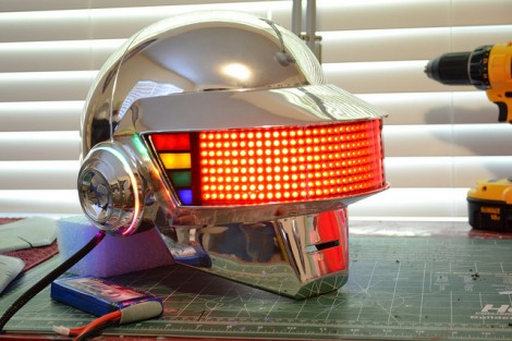
His Daft Punk-esque lamp can be programmed to display just about anything from color patterns to video game sprites, and it can also be timed to music if desired. We think it looks great, and could make for a nice wall hanging if he ever got sick of the stand. While the wire wrap technique sounds like it sped up the development of this project significantly, we would be interested in hearing how it holds up after a few months of use.

Check out the trio of videos embedded below to see the Lampduino in action.

Continue reading “LED Floor Lamp Really Ties The Room Together”