If you’re like us, it’s hard to walk through an Ikea without mentally hacking everything there into something else. The salad bowl? Parabolic antenna. Drawer slides? Linear motion rails. Storage containers? Etching tank. We admit that we still haven’t figured out what to do with that 1,000-pack of tea lights.
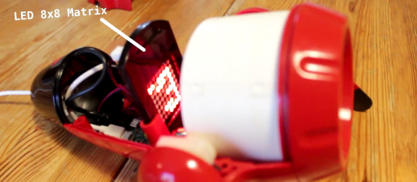
[Alain Mauer] pulled off an Ikea hack that we’ve always dreamed about. In particular, he took the Sprida projector lamp and wedged an 8×8 LED matrix and Raspberry Pi Zero into it.
The lamp in question is essentially a slide projector for kids. Before [Alain] got to it, it had an LED in the back, a mount for a slide in the middle, and a focusing lens on the front. His mod is simplicity itself: remove the LED and transparency, and place the LED matrix in the focal plane where the slide used to be. Reverse images on the LED in software to compensate for the lens, and you’re done.
The video says “Raspberry Pi Zero with WiFi” and the project title promises “IoT”, but we don’t see the WiFi in the build. We’re guessing that [Alain] will get around to it — it’s easily doable. (Doh! There’s a tiny USB WiFi dongle providing the obligatory wireless connection.) Anyway, the point is the projection, and we love it, and we’d be lying if we said it didn’t make us think about RGB matrices.
Continue reading “Ikea Projection Lamp Makeover Adds LED Matrix And Raspberry Pi Zero”