There’s a lot of laboratory equipment out there that the casual hobbyist will never need to use, but that doesn’t mean you wouldn’t snap it up if the price is right. That’s what happened when [Tom Verbeure] saw a 1980s digital delay generator at a flea market for $40. Not only is it an excellent way to learn something about these devices, but it also provides a fascinating opportunity to troubleshoot and hopefully fix it. Such was also the case with this Stanford Research Systems (SRS) DG535 that turned out to be not only broken, but even features an apparently previously triggered self-destruct feature.
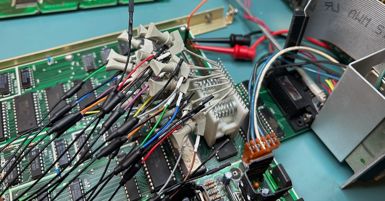
These devices are pretty basic, with this specimen incorporating a Z80 MPU in addition to digital and analog components to provide a programmable delay with 12.5 nanosecond resolution on its output channels after the input trigger is sensed. For that reason it was little surprise that the problem with the device was with its supply rails, of which a few were dead or out of spec, along with a burned-out trace.
 Where the self-destruct feature comes into play is with the use of current boosting resistors around its linear regulators. Although these provide a current boost over what the regulator can provide, their disadvantages include a tendency towards destruction whenever the load on the supply rail decreases. This could for example occur when you’re debugging an issue and leave some of the PCBs disconnected.
Unsurprisingly, this issue caused the same charred trace to reignite during [Tom]’s first repair attempt, but after working up the courage over the subsequent 18 months the second repair attempt went much better, also helped by the presence of the mostly correct original board schematics.
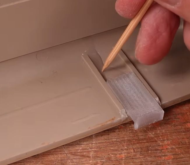
Ultimately the fixes were relatively modest, involving replacing a discrete diode bridge with an integrated one, fixing the -9 V rail with a bodge wire, and replacing the LCD with its busted AC-powered backlight with a modern one with a LED backlight. Fortunately running the 5 V rail at 7 V for a while seemed to have caused no readily observable damage, nor did flipping connectors because of SRS’ inconsistent ‘standards’ for its connector orientations.
Sadly, when [Tom] emailed SRS to inquire about obtaining an updated schematic for this unit — which is currently still being sold new for $4,495 — he merely got told to send his unit in for repair.

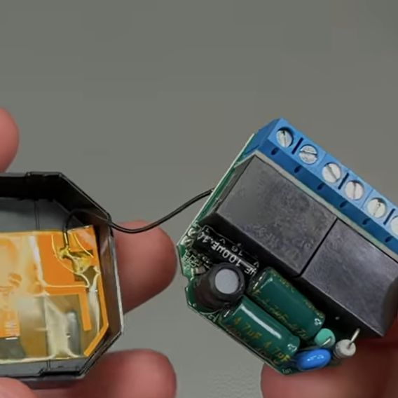 Part of any self-respecting Smart Home, smart relays are useful for switching and monitoring loads that do not plug into an outlet. This also makes them a lot more integrated, and thus, a long lifespan is very welcome. Unfortunately, the popular Shelly 2.5 smart relays seem to be having a bit of a design flaw as they’re dying in droves once their 2-year warranty period is up. The cause and repair are covered in a recent [VoltLog] video on YouTube.