As many readers may already know, when I’m not featuring your projects or working on the mooltipass I try to make simple things that may be useful to electronics enthusiasts. My latest creation is a simple bill of materials generation tool, which can also do simple stock management. Unfortunately for Linux users, this utility is made using Visual Basic functions in an Excel file.
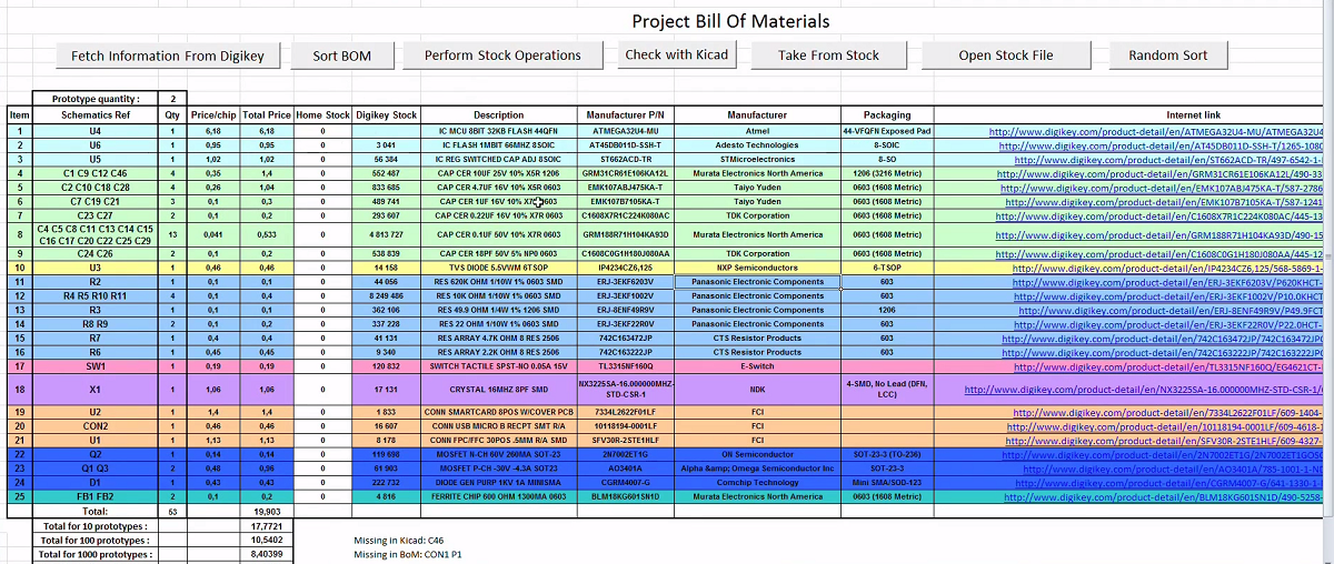
It works fairly simply: just enter your schematics’ components references in the excel sheet, along with the corresponding Digikey webpage address. Click on the “fetch” button and the script will automatically get all your component characteristics from the internet and tell you the component costs depending on the number of prototypes you want to make. Then click the “sort BoM” button and your BoM will automatically be sorted by component type and value. Another functionality allows you to check that all the components present in your BoM are also present on the (very simple) Kicad generated one. Finally, using another Excel sheet containing your current stock, the Bill of Materials will let you know if you have enough components for the assembly stage. A video of the tool in action is embedded after the break, and you can download the BoM template here (.XLSM file) and the corresponding stock file there (.XLSM file).
Continue reading “A Simple (and Dirty) Bill Of Materials And Stock Management Utility”