Power outage? For the average citizen it’s very easy to take electricity for granted. Go a few hours or more without it though, and you’ll suddenly be reminded just what a luxury it is. During an emergency situation, sometimes you have to come up with alternative methods to get the job done. This human powered cell phone charger is a great example.
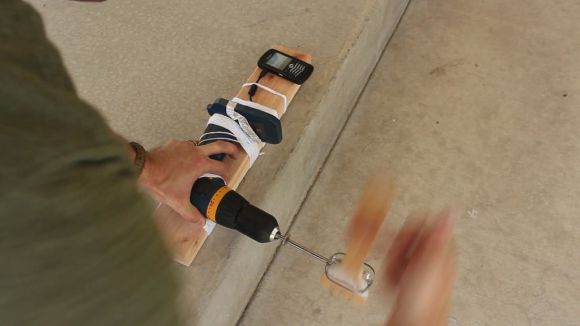
Using just a few ordinary around the house items, [The King of Random] turned a cordless electric drill into a human powered electrical generator. If the drill is run in reverse and cranked by hand, the generated energy can be transferred through the battery terminals to a connected device. So, he cut a USB charger cable in half and wired it up to the terminals to be able to charge his cell phone. Some yarn, a salad fork, a mixing beater, a scrap 2″x4″, some aluminum foil, and scotch tape were the only other materials he used. Using this technique, a totally dead phone battery was charged in around 3 hours.
Remember that this method is only intended to be used in an emergency, not as every day practice. Using these methods could potentially overheat or damage your gear, so be careful.
Check out the MacGyver worthy video tutorial after the break.
[via Neatorama]
Continue reading “Human Powered Emergency Cell Phone Charger”