An LM386 Oscillator Thanks To Tungsten Under Glass

Once ubiquitous, the incandescent light bulb has become something of a lucerna non grata lately. Banned from home lighting, long gone from flashlights, and laughed out of existence by automotive engineers, you have to go a long way these days to find something that still uses a tungsten filament.

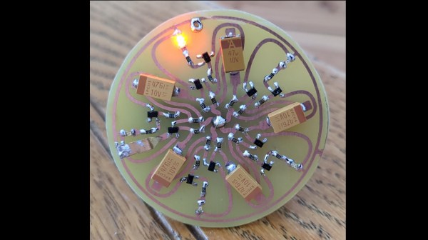
Strangely enough, this lamp-stabilized LM386 Wien bridge oscillator is one place where an incandescent bulb makes an appearance. The Wien bridge itself goes back to the 1890s when it was developed for impedance measurements, and its use in the feedback circuits of vacuum tube oscillators dates back to the 1930s. The incandescent bulb is used in the negative feedback path as an automatic gain control; the tungsten filament’s initial low resistance makes for high gain to kick off oscillation, after which it heats up and lowers the resistance to stabilize the oscillation.

For [Grug Huler], this was one of those “just for funsies” projects stemming from a data sheet example circuit showing a bulb-stabilized LM386 audio oscillator. He actually found it difficult to source the specified lamp — there’s that anti-tungsten bias again — but still managed to cobble together a working audio oscillator. The first pass actually came in pretty close to spec — 1.18 kHz compared to the predicted 1.07 kHz — and the scope showed a very nice-looking sine wave. We were honestly a bit surprised that the FFT analysis showed as many harmonics as it did, but all things considered, the oscillator performed pretty well, especially after a little more tweaking. And no, the light bulb never actually lights up.

Thanks to [Grug] for going down this particular rabbit hole and sharing what he learned. We love builds like this that unearth seemingly obsolete circuits and bring them back to life with modern components. OK, calling the LM386 a modern component might be stretching things a bit, but it is [Elliot]’s favorite chip for a reason.

Continue reading “An LM386 Oscillator Thanks To Tungsten Under Glass”

Install ChimeraOS And Never Leave The Sofa

There are some projects that initially don’t seem to make sense, but actually turn out to have valid use cases. ChimeraOS appears to be one of those. The idea is that if you own a gaming PC, but it is not necessarily located where you want to be all the time (like in a gaming den or office for example) then ChimeraOS allows you to play games on it remotely via a local machine. That machine may be a media PC attached to your main TV, or perhaps a mobile device like a steam deck.

With support for AMD GPUs only, there is one issue with deployment — if you’re an Nvidia owner you’re out of luck — the premise is to be able to boot up into a gaming-friendly environment with minimal fuss. Hook up a controller and you’re good to go. Support is also there for a few mobile devices, specifically some Aokzoe, Aya Neo, and OneXPlayer devices as well as some preliminary support for the Asus ROG Ally not to mention the Steam Deck as we touched on earlier. From a software perspective, it obviously supports the Steam platform but also Epic Games, Good Old Games (GOG), and tentatively a mention of console platforms. Sadly the website doesn’t mention much detail on that last bit, but there are some tantalizing hints in the project’s Twitter/X/whatever feed. Reading the release notes, there are mentions of PCSX2 (Playstation 2) Super Game Boy and Atari platforms, so digging into the GitHub repo might be instructive, or you know, actually installing it and trying. This scribe doesn’t own an AMD GPU so that isn’t an option, but do drop us a line in the comments if you’ve tried it and how it works for you.

Many of us at Hackday are avid gamers, especially of the retro kind, which is why we really like these projects. Here’s a nice game controller you can print yourself. For self-builds, there’s nothing quite like the satisfaction of a DIY arcade machine, but what if you think outside the box?

Automated Drone Takes Care Of Weeds

Commercial industrial agriculture is responsible for providing food to the world’s population at an incredibly low cost, especially when compared to most of human history when most or a majority of people would have been involved in agriculture. Now it’s a tiny fraction of humans that need to grow food, while the rest can spend their time in cities and towns largely divorced from needing to produce their own food to survive. But industrial agriculture isn’t without its downsides. Providing inexpensive food to the masses often involves farming practices that are damaging to the environment, whether that’s spreading huge amounts of synthetic, non-renewable fertilizers or blanket spraying crops with pesticides and herbicides. [NathanBuildsDIY] is tackling the latter problem, using an automated drone system to systemically target weeds to reduce his herbicide use.

The specific issue that [NathanBuildsDIY] is faced with is an invasive blackberry that is taking over one of his fields. To take care of this issue, he set up a drone with a camera and image recognition software which can autonomously fly over the field thanks to Ardupilot and a LiDAR system, differentiate the blackberry weeds from other non-harmful plants, and give them a spray of herbicide. Since drones can’t fly indefinitely, he’s also build an automated landing pad complete with a battery swap and recharge station, which allows the drone to fly essentially until it is turned off and uses a minimum of herbicide in the process.

The entire setup, including drone and landing pad, was purchased for less than $2000 and largely open-source, which makes it accessible for even small-scale farmers. A depressing trend in farming is that the tools to make the work profitable are often only attainable for the largest, most corporate of farms. But a system like this is much more feasible for those working on a smaller scale and the automation easily frees up time that the farmer can use for other work. There are other ways of automating farm work besides using drones, though. Take a look at this open-source robotics platform that drives its way around the farm instead of flying.

Thanks to [PuceBaboon] for the tip!

Continue reading “Automated Drone Takes Care Of Weeds”

Laser Engraver Uses All Of The DVD Drive

For the last ten to fifteen years, optical drives have been fading out of existence. There’s little reason to have them around anymore unless you are serious about archiving data or unconvinced that streaming platforms will always be around. While there are some niche uses for them still, we’re seeing more and more get repurposed for parts and other projects like this tabletop laser engraver.

The build starts with a couple optical drives, both of which are dismantled. One of the shells is saved to use as a base for the engraver, and two support structures are made out of particle board and acrylic to hold the laser and the Y axis mechanism. Both axes are made from the carriages of the disassembled hard drives, with the X axis set into the base to move the work piece. A high-output laser module is fitted to the Y axis with a heat sink, and an Arduino and a pair of A4988 motor controllers are added to the mix to turn incoming G-code into two-dimensional movement.

We’ve actually seen a commercial laser engraver built around the same concept, but the DIY approach is certainly appealing if you’ve got some optical drives collecting dust. Otherwise you could use them to build a scanning laser microscope.

Continue reading “Laser Engraver Uses All Of The DVD Drive”

A Hobson’s Coupler Leads To A Weird Engine

You want to join two shafts. What do you need? A coupler, of course. If the shafts don’t line up, you might consider an Oldham coupler. But what if the shafts are at a 90-degree angle to each other? Then you need a Hobson’s coupler. [Robert Murray-Smith] has the 3D printed hookup for you and a video that you can see below.

The part isn’t all 3D printed, though. You do need some bearings and steel rods. [Robert] proposes using this to couple a windmill’s blades to a generator, although we assume some loss is involved compared to a standard shaft. However, we’ve heard that the coupler, also called a Hobson’s joint or a stirrup joint, is actually pretty efficient. However, you rarely see these in practice because most applications will use a gear train employing a bevel gear.

While it may not be practical, the second video below shows an elbow engine that would look undeniably cool on your desk. By making some changes, you can create a Cardan joint which happens to be half of what you think of as a universal joint. The Hobson coupler and the Cardan joint seem to be made for each other, as you’ll see in the video.

We aren’t sure what we want to make with all these mechanisms, but as [Robert] points out, with new materials and techniques, these mechanisms might have a role to play in future designs, even though they have been mostly discarded.

There are, of course, many kinds of couplings. Then again, not all useful joints have to move.

Continue reading “A Hobson’s Coupler Leads To A Weird Engine”

Canadian Engineers? They Have A Ring About Them

How can you spot an engineer? It can be tricky, but it is a little easier in Canada. That’s because many Canadian engineers have been through the Ritual of the Calling of an Engineer and wear an iron or steel ring to symbolize their profession. The ring has a very odd history that originated in 1922 as the brainchild of Professor H. E. T. Haultain. While he may not be a recognizable name, at least one famous person was involved with creating the Ritual.

H. E. T. Haultain

The ring itself has facets on the outer surface, and you wear it on the little finger of your dominant hand. Originally handmade, the ring reminds the wearer of the engineer’s moral, ethical, and professional commitment. In addition to being a visible reminder, the ring is made to drag slightly as you write or draw, as a constant reminder of the engineer’s obligation. With more experience, the ridges wear down, dragging less as you get more experience.

There is a rumor that the first rings were made from the metal of a bridge that collapsed due to poor design, but this appears untrue. The presentation ceremony is understated, with limited attendance and very little publicity.

Continue reading “Canadian Engineers? They Have A Ring About Them”

PentaBlinky – When One LED Is Not Blinky Enough

[michimartini] over on Hackaday.io loves playing with multivibrator circuits, and has come across a simple example of a ring oscillator. This is a discrete transistor RC-delay design utilizing five identical stages, each of which has a transistor that deals with charging and discharging the timing capacitor, passing along the inverted signal to its nearest neighbor. The second transistor isn’t strictly needed and is only there to invert the signal in order to drive the LED. When the low pulse passes by the LED lights, without it you’d see all the LEDs lit bar one, which doesn’t look as good.

Compare this with an astable multivibrator to understand how it works

Essentially this circuit is just the classic astable multivibrator circuit that has been split in half and replicated so that the low pulse propagates through more stages than just the two, but thinking about it as a single stage doesn’t work so well until you draw in a couple of neighbors to help visualize the behavior better.

[michimartini] does lament that the circuit starts up in a chaotic fashion and needs a quick short applying to one transistor element in order to get it to settle into a steady rhythm. Actually, that initial behaviour could be interesting in itself, especially as the timing changes with voltage and temperature.

Anyway, we like the visual effect and the curvy organic traces. It would make a neat pin badge. Since we’re thinking about blinkies, here are couple of somewhat minimalist attempts, the world’s smallest blinky, and an even smaller one. Now, who doesn’t love this stuff?

Continue reading “PentaBlinky – When One LED Is Not Blinky Enough”