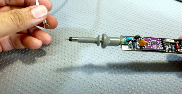
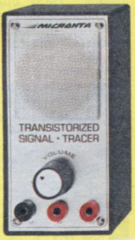
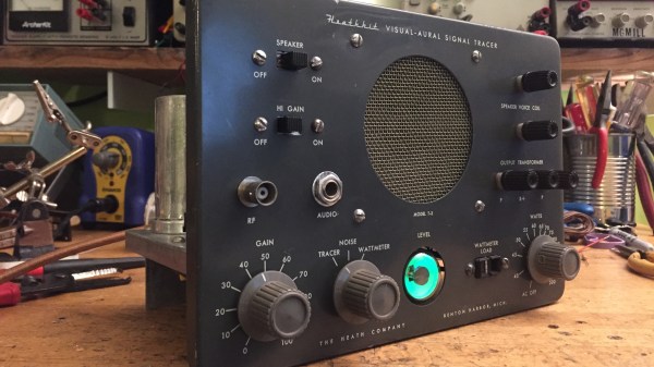
Active Signal Tracer Probe Has AGC

[Electronics Old and New] has a new version of one of his old projects. The original project was an active probe. He took what he learned building that probe and put it into a new probe design. He also added automatic gain control or AGC. You can see a video explanation of the design below. The probe is essentially a high-impedance input using a JFET that can amplify audio or demodulated RF signals, which is a handy device to have when troubleshooting radios.

The audio amplifier is a simple LM386 circuit. The real work is in the input stage and the new AGC circuit. Honestly, we’ve used the amplifier by itself for a similar function, although the raw input impedance of the chip is only about 50K and is less in many circuits that use a pot on the input. Having a JFET buffer and an RF demodulating diode is certainly handy. You’d think the AGC block would be in the audio stage. However, the design uses it ahead of the detector which is great as long as the amplifier can handle the RF frequency you are interested in. In this case, we think he’s mostly working on old tube AM radios, so the max signal is probably in the neighborhood of 1 MHz.

A similar device was a Radio Shack staple for many years

The module is made to amplify an electret microphone using a MAX9814 which has AGC. The module had a microphone that came off for this project. The datasheet doesn’t mention an upper frequency limit, but a similar Maxim part mentions its gain is greater than 5 at 600 kHz, so for the kind of signals this is probably used for, it should work well. We wondered if you could use the module and dispense with the JFET input. The chip probably has a pretty high input impedance, but the datasheet doesn’t give a great indication.

For years we used a signal tracer from Radio Shack which — if we could still find it — now has an LM386 inside of it after the original electronics failed decades ago. In those days, fixing an AM radio involved either using a device like this to find where you did and didn’t have a signal or injecting signals at different points in the radio. Two sides of the same coin. For example, if you could hear a signal at the volume control — that indicated the RF stages were good and you had a problem on the audio side. Conversely, if you injected a signal at the volume control, not hearing would mean the same thing. Once you knew if the problem was in the RF or AF side, you’d split that part roughly in half and repeat the operation until you were down to one bad stage. Of course, you could use signal generators and scopes, but in those days you weren’t as likely to have those.

Heathkit, of course, had their own version. It even had on of those amazing magic eye tubes.

Continue reading “Active Signal Tracer Probe Has AGC”

Reliving Heathkit’s Glory Days Through A Teardown And Rebuild

In its heyday, the experience offered by the Heath Company was second to none. Every step of the way, from picking something out of the Heathkit catalog to unpacking all the parts to final assembly and testing, putting together a Heathkit project was as good as it got.

Sadly, those days are gone, and the few remaining unbuilt kits are firmly in the unobtanium realm. But that doesn’t mean you can’t tear down and completely rebuild a Heathkit project to get a little taste of what the original experience was like. [Paul Carbone] chose a T-3 Visual-Aural signal tracer, a common enough piece that’s easy to find on eBay at a price mere mortals can afford. His unit was in pretty good shape, especially for something that was probably built in the early 1960s. [Paul] decided that instead of the usual recapping, he’d go all the way and replace every component with fresh ones. That proved easier said than done; things have changed a lot in five decades, and resistors are a lot smaller than they used to be. Finding hookup wire to match the original was also challenging, as was disemboweling some of the electrolytic cans so they could be recapped. The finished product is beautiful, though — even the Magic Eye tube works — and [Paul] reports that the noise level is so low he wasn’t sure if turned it on at first.

We’ve covered the rise and fall of Heathkit, as well as their many attempted comebacks, including an inexplicable solder-free radio and the “world’s most reliable” clock. Looking at these offerings, we think [Paul] may be onto something here.

Retrotechtacular: TV Troubleshooting

As technology advances, finding the culprit in a malfunctioning device has become somewhat more difficult. As an example, troubleshooting an AM radio is pretty straightforward. There are two basic strategies. First, you can inject a signal in until you can hear it. Then you work backwards to find the stage that is bad. The other way is to trace a signal using a signal tracer or an oscilloscope. When the signal is gone, you’ve found the bad stage. Of course, you still need to figure out what’s wrong with the stage, but that’s usually one or two transistors (or tubes) and a handful of components.

A common signal injector was often a square wave generator that would generate audio frequencies and radio frequency harmonics. It was common to inject at the volume control (easy to find) to determine if the problem was in the RF or audio sections first. If you heard a buzz, you worked backwards into the RF stages. No buzz indicated an audio section problem.

A signal tracer was nothing more than an audio amplifier with a diode demodulator. Starting at the volume control was still a good idea. If you heard radio stations through the signal tracer, the RF section was fine. Television knocked radio off of its pedestal as the primary form of information and entertainment in most households, and thus the TV repair industry was created.

Continue reading “Retrotechtacular: TV Troubleshooting”