A 3D-printed mechanism is clamped between the jaws of a pair of calipers, which are surrounded by 3D-printed covers. A hammer is resting against one of the jaws, and a man's gloved hand is holding the calipers.

Embossing Precision Ball Joints For A Micromanipulator

[Diffraction Limited] has been working on a largely 3D-printed micropositioner for some time now, and previously reached a resolution of about 50 nanometers. There was still room for improvement, though, and his latest iteration improves the linkage arms by embossing tiny ball joints into them.

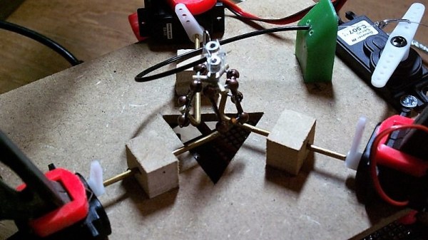
The micro-manipulator, which we’ve covered before, uses three sets of parallel rod linkages to move a platform. Each end of each rod rotates on a ball joint. In the previous iteration, the parallel rods were made out of hollow brass tubing with internal chamfers on the ends. The small area of contact between the ball and socket created unnecessary friction, and being hollow made the rods less stiff. [Diffraction Limited] wanted to create spherical ball joints, which could retain more lubricant and distribute force more evenly.

The first step was to cut six lengths of solid two-millimeter brass rod and sand them to equal lengths, then chamfer them with a 3D-printed jig and a utility knife blade. Next, they made two centering sleeves to hold small ball bearings at the ends of the rod being worked on, while an anti-buckling sleeve surrounded the rest of the rod. The whole assembly went between the jaws of a pair of digital calipers, which were zeroed. When one of the jaws was tapped with a hammer, the ball bearings pressed into the ends of the brass rod, creating divots. Since the calipers measured the amount of indentation created, they was able to emboss all six rods equally. The mechanism is designed not to transfer force into the calipers, but he still recommends using a dedicated pair.

In testing, the new ball joints had about a tenth the friction of the old joints. They also switched out the original 3D-printed ball mount for one made out of a circuit board, which was more rigid and precisely manufactured. In the final part of the video, he created an admittedly unnecessary, but useful and fun machine to automatically emboss ball joints with a linear rail, stepper motor, and position sensor.

On such a small scale, a physical ball joint is clearly simpler, but on larger scales it’s also possible to make flexures that mimic a ball joint’s behavior.

A camera-based microscope is on a stand, looking down towards a slide which is held on a plastic stage. The stage is held in place by three pairs of brass rods, which run to red plastic cranks mounted to three stepper motors. On the opposite side of each crank from the connecting rod is a semicircular array of magnets.

Designing An Open Source Micro-Manipulator

When you think about highly-precise actuators, stepper motors probably aren’t the first device that comes to mind. However, as [Diffraction Limited]’s sub-micron capable micro-manipulator shows, they can reach extremely fine precision when paired with external feedback.

The micro-manipulator is made of a mobile platform supported by three pairs of parallel linkages, each linkage actuated by a crank mounted on a stepper motor. Rather than attaching to the structure with the more common flexures, these linkages swivel on ball joints. To minimize the effects of friction, the linkage bars are very long compared to the balls, and the wide range of allowed angles lets the manipulator’s stage move 23 mm in each direction.

To have precision as well as range, the stepper motors needed closed-loop control, which a magnetic rotary encoder provides. The encoder can divide a single rotation of a magnet into 100,000 steps, but this wasn’t enough for [Diffraction Limited]; to increase its resolution, he attached an array of alternating-polarity magnets to the rotor and positioned the magnetic encoder near these. As the rotor turns, the encoder’s local magnetic field rotates rapidly, creating a kind of magnetic gear.

A Raspberry Pi Pico 2 and three motor drivers control this creation; even here, the attention to detail is impressive. The motor drivers couldn’t have internal charge pumps or clocked logic units, since these introduce tiny timing errors and motion jitter. The carrier circuit board is double-sided and uses through-hole components for ease of replication; in a nice touch, the lower silkscreen displays pin numbers.

To test the manipulator’s capabilities, [Diffraction Limited] used it to position a chip die under a microscope. To test its accuracy and repeatability, he traced the path a slicer generated for the first layer of a Benchy, vastly scaled-down, with the manipulator. When run slowly to reduce thermal drift, it could trace a Benchy within a 20-micrometer square, and had a resolution of about 50 nanometers.

He’s already used the micro-manipulator to couple an optical fiber with a laser, but [Diffraction Limited] has some other uses in mind, including maskless lithography (perhaps putting the stepper in “wafer stepper”), electrochemical 3D printing, focus stacking, and micromachining. For another promising take on small-scale manufacturing, check out the RepRapMicron.

Continue reading “Designing An Open Source Micro-Manipulator”

Active Ball Joint Uses Spherical Gear

A common CAD operation is to take a 2D shape and extrude it into a 3D shape. But what happens if you take a gear and replicate it along a sphere and then rotate it and do it again? As you can see in the video below, you wind up with a porcupine-like ball that you can transfer power to at nearly any angle. There’s a paper describing this spherical gear as part of an active ball joint mechanism and even if you aren’t mechanically inclined, it is something to see.

The spherical gear — technically a cross spherical gear — is made from PEEK and doesn’t look like it would be that difficult to fabricate. There’s also a simpler version known as a monopole gear in the drive system that provides three degrees of freedom.

Continue reading “Active Ball Joint Uses Spherical Gear”

Dainty Delta Is About As Small As A Robot Can Be

There’s something mesmerizing about delta robots. Whether they are used at a stately pace for a 3D-printer or going so fast you can barely see them move in a pick and place machine, the way that three rotary actuators can work together to produce motion in three axes is always a treat to watch. Especially with a delta robot as small as this one.

[KarelK16] says this is one of those “just because I can” projects with no real application. And he appears to have been working on it for a while; the video below is from eight years ago. Regardless, the post is new, and it’s pretty interesting stuff. The tiny ball joints used in the arms are made from jewelry parts; small copper crank arms connect the three upper arms to micro-servos. The manipulator [KarelK16] attached is very clever, too – rather than load down the end of the arms with something heavy, a fourth servo opens an closes a flexible plastic grasper through a Bowden cable. It’s surprisingly nimble, and grasps small objects firmly.

There are certainly bigger deltas – much bigger – and more useful ones, too, but we really like this build. And who knows – perhaps model robotics will join model railroading as a hobby someday. If it does, [KarelK16]’s diminutive delta might be the shape of things to come.

Continue reading “Dainty Delta Is About As Small As A Robot Can Be”