A Soft Soldering Jig For Hard Projects

We’ve seen some absolutely gorgeous freeform circuit sculptures. There’s a mystic quality to taking what has normally been hidden away for safety and reliability reasons and putting it on display for everyone to see. Of course, creating these unique circuit sculptures takes considerable time and effort. [Inne] created several silicone soldering jigs to help with these tricky joints.

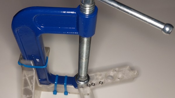
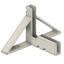
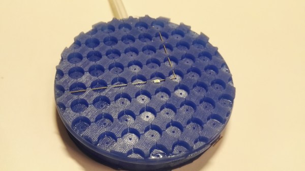
While a vice or helping hands is crucial for many joints, when dealing with tiny SMD components and exacting angles, you need something a little more specialized. Double-sided tape is often recommended, but heat ruins the adhesive and SMD components like to stick to soldering iron tips. Since silicone tends to be heat resistant, it makes a decent material for soldering on. [Inne] uses a city analogy with the cups for soldering called plazas, each with a hole (called a manhole) leading to a foot-switch vacuum pump to keep parts in place. The OpenSCAD code is available on GitHub under a GPLv3 license. It generates a two-part mold that you can cast in A-8/A-15 silicone.

It’s a clever project that makes it far easier to assemble gorgeous circuit sculptures. We love the design and thought that went into it, particularly the naming scheme as we often find appropriately naming variables in OpenSCAD quickly becomes difficult.

DIY guide saw

A Beautiful DIY Guided Saw

[JSK-koubou] has quite the talent for creative woodwork, particularly building interesting tools or improving existing ones. This recent project (multiple build videos below: part 1, part 2, and part 3) is a very flexible type of guided pull saw, whereby a fine-toothed saw blade is fixed in the bed, and the workpiece is pulled over it it. By fixing it at a shallow angle, and enabling the blade to be raised up through the bed, the workpiece can be progressively cut by simply pulling it over the blade, then winding it up a little until the final cut length is achieved.

From a construction perspective, the tool is all-metal, built from a collection of the off-the-shelf parts, and thick, hand-cut aluminium alloy plate, nary a CNC tool in sight. The only unusual component is the saw blade itself, 
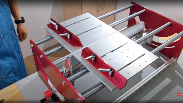
which might be a bit tricky to track down if you were so inclined to reproduce the build. It appears (well if you believe the auto-translation by Google Lens, anyway) to be a spare blade for a commercial guide saw available in Japan at least.

We found it particularly pleasing to see the use of a home-built anodizing setup to give it a bit of a jazzy color scheme for some of the plates, just because. Like with many of the build videos from this YouTuber, it is well worth watching all of them, if only just to gather a few ideas for one’s own workspace, if you can stop yourself getting distracted looking at all the other neat tools he uses on the way.

DIY tool builds are not uncommon in these parts, here’s a neat DIY combo table-based project, and here’s a homebrew auto-lowering metal bandsaw which could be a real timesaver.

Continue reading “A Beautiful DIY Guided Saw”

Homebrew Curve Tracer Competes With The Big Guns

When we first saw the VBA curve tracer, we thought it might have something to do with Visual Basic for Applications. But it turns out it is a mash up of the names of the creators: [Paul Versteeg], [Bud Bennett], and [Mark Allie]. [Paul] designed an original prototype back in 2017. Since then, the project has grown and lessons were learned. The final curve tracer is pretty impressive in more ways than one.

If you’ve never used a curve tracer, they allow you to characterize components using their characteristic curve of voltage versus current. You use an oscilloscope as an output device. This instrument is often used by engineers trying to understand or match devices like diodes, transistors, or — in some cases — even tubes. So if you want to measure the collector-emitter breakdown voltage, for example, or the collector cutoff current, this is your go-to device. You can also match gains in circuits where that matters (for example, a push-pull circuit where two transistors amplify different parts of the same signal).

If you want to understand more about how it works, there are a series of blog posts covering the evolution of the device. You can also find the design files on GitHub. There is also a handy post showing many types of measurements you might want to make.

This is a good-looking project. We’ve seen it done on the cheap, but slowly. Or spend $15 and do better. We doubt any of these have high enough voltages to do most tubes, but they made the same basic instrument for tubes back in the 1950s.

Upside-down c-clamp held in a frame, forming a crude press

C-Clamp Becomes Light-Duty Arbor Press

[ThingaUser] made a tool to solve a specific problem of theirs, but the design also happens to be a pretty good way to turn a c-clamp into a poor man’s light duty arbor press.

The frame is made for a common 4-inch c-clamp.

The problem they had was a frequent need to press nuts and occasionally bearings into other parts. Some kind of press is really the best tool for the job, but rather than buy a press, they opted to make their own solution. By designing and 3D printing an adapter for a common 4-inch c-clamp, a simple kind of light duty press was born.

Sure, one has to turn the handle on the clamp to raise and lower the moveable jaw, and that’s not the fastest operation. But the real value in the design is that the clamp can now stand by itself on a tabletop, leaving the operator to dedicate one hand to manipulating the part to be pressed, while twisting the clamp’s handle with the other hand. There’s no need for a third hand to keep the clamp itself stable in the process. As a bonus, it can print without supports and the clamp secures with zip ties; no other fasteners or glue needed.

Not all c-clamps are the same, so there is a risk that this frame that fits [ThingaUser]’s clamp might not fit someone else’s. In those cases, it’s best to have access to not just the STL file, but also to a version in a portable CAD format like STEP to make it easy to modify. But there are still ways to make changes to an STL that isn’t quite right.