Vintage DACs And A Raspberry Pi

DAC

Before the days of iPod docks in every conceivable piece of audio equipment, most devices were actually built very well. Most shelf top equipment usually came with well designed circuits using quality components, and late 90s CD players were no exception. [Mariosis] heard of some very nice DACs found in some of these units and decided to take one out for a spin. He’s using a Raspberry Pi to play audio with the DAC found in a late 90s Kenwood CD player.

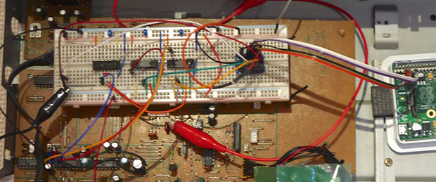
After fortune favored a CD player with a dead drive on [Mariosis]’ workbench, he dug up the service manual and found some interesting chips – a PCM56 DAC, a little bit of logic, and an SM5807 oversampling chip that does all the conversion for the DAC.

This oversampling chip uses an I2S – not I2C – bus to carry the data from the CD to the DAC. There is, of course, an I2S driver for the Raspi, but the first attempts at playing audio didn’t result in anything. It turned out there was a problem with what the oversampler expected – the ‘standard’ I2S signal delays the data one tick behind the LRCLK signal.

There are two ways to fix this problem: programming a kernel driver, or building some custom logic to fix the problem. Obviously breaking out some flip-flops and NOR gates was the cooler option, giving [Mariosis] a great sounding stereo with a vintage DAC.

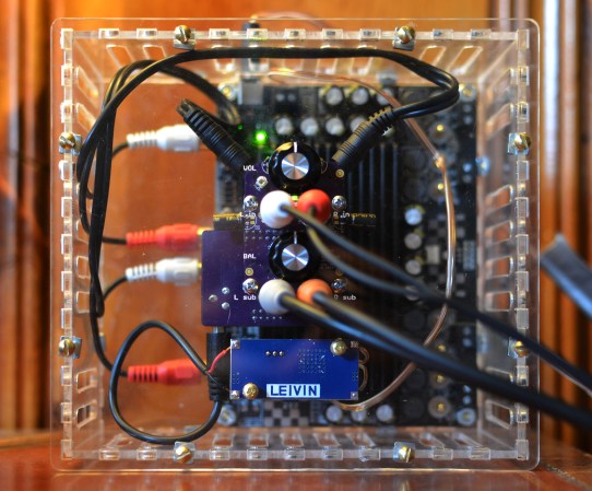
Building A ‘high-end’ USB Audio DAC

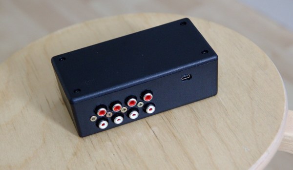
As [Jan-Erik] had already built a simple USB connected Digital-to-Analog Converter (DAC), he decided to make the high-end version of it.

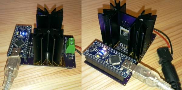
The prototype you see in the picture above is based on:

  • the PCM2707C from Texas Instruments which takes care of the USB communication and outputs I2S audio data
  • the PCM1794A, a 132dB SNR 24-bit 192kHz DAC which receives I2S protocol
  • the OPA4134, a high performance audio operational amplifier

The on-board +3.3V and -5V voltages are generated by inductor-less power supplies. As [Jan-Erik] mentions in his write-up, the ‘high-end’ was put between single quotes because the PCB is single sided and uses through hole passive components. The board was designed using Kicad, etched by himself and put in a machined enclosure. All the production files can be downloaded from his website so you may produce it within a day.

The Difference Between Bitcrushers And Sample Rate Reducers

bit

If you look around a few electronic music forums, you’ll see a lot of confusion over the difference between a bitcrusher – a filter that reduces the bit depth of an audio signal – and a sample rate reducer – a filter that does exactly what its name implies. With the popularization of 8-bit and retro synth music, this difference is obviously of grave import of concern to saints and kings alike. [Michael] is more than happy to walk us through the difference with real-time sample and bit rate adjustment with his audio hacker board.

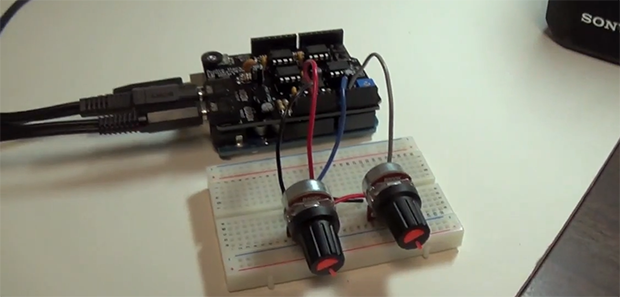
The audio hacker board is an Arduino shield with a 12-bit DAC and a 12-bit ADC. With two 1/8″ jacks and a pair of pots, [Michael] was easily able to whip up a sketch that is able to adjust the sample rate and bit depth of an audio signal in real-time.

Contrary to nearly everyone’s opinion of what ‘8-bit’ music is, it’s actually the sample rate that makes music sound like a cassette deck jury rigged into a Nintendo Entertainment System. Reducing the bitrate just makes any audio source sound louder and worse.

Check out the excellent demo video of the effect of bitcrushers and sample rate reducers below.

Continue reading “The Difference Between Bitcrushers And Sample Rate Reducers”

Building An Audio Box Out Of Thrown Away Boards

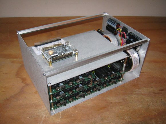
The last time [Mark] was at the scrap yard, he managed to find the analogue input and output cards of an old Akai DR8 studio hard drive recorder. These cards offered great possibilities (8 ADC inputs, 12 DAC outputs) so he repaired them and made a whole audio system out of them.

The repair only involved changing a couple of low dropout regulators. Afterwards, [Mark] interfaced one of his CPLD development boards so he could produce some sine waves and digitize signals generated from a PC based audio test unit. He then made the frame shown in the picture above and switched to an Altera Cyclone IV FPGA. To complete his system, he designed a small board to attach a VGA screen,  and another to use the nRF24L01 wireless module.

Inside the FPGA, [Mark] used a NIOS II soft core processor to orchestrate the complete system and display a nice user interface. He even made another system with an USB host plug to connect MIDI enabled peripherals, allowing him to wirelessly control his creation.

ATmega1284 As An 8-voice 32 KHz Synthesizer

A couple of things strike us about this 8-voice 32 kHz synthesizer. First is the cleanliness of the prototype. As you can see, each part has plenty of room on its own board and all are interconnected by 10-pin IDC ribbon connectors. But you’ll have to see the video after the break to enjoy the impressive sound that this puts out. You’ll hear it play the Super Mario Bros. theme; it does it with passion!

To get audio from the digital microcontroller [Mike] built his own R2R digital to analog converter. The resistor ladder is built from sixteen resistors, which feed a rail-to-rail amplifier. The sound is mono but the playback is polyphonic thanks to the work done by the ATmega1284. It is reading MIDI commands coming in from an external controller (we assume it’s the computer on which the hardware is sitting). The chip’s 128 KB of Flash memory leave plenty of room to store samples, which are selected from a lookup table based on the MIDI data. If more than one sample is to be played the chip averages the data and sets the 8-bit output port accordingly.

Continue reading “ATmega1284 As An 8-voice 32 KHz Synthesizer”

An Adafruit Raspberry Pi Extravaganza

The folks at Adafruit are busy as a bee working on bringing some of their really cool boards to the Raspberry Pi platform. Here’s a few that came in over the last few days:

16 servos is almost too many

Servos require a PWM output but the Raspi only has hardware support for PWM on a single GPIO pin; certainly not enough to build a gigantic, city-leveling robot. [Kevin] over at Adafruit put together a tutorial for using this 16 channel servo driver with the Raspi.

12 bit DAC

With only one PWM pin and no analog out, it was only a matter of time before someone hooked up the Adafruit 12 bit DAC to the Raspberry Pi.

16×2 LCD displays

Both the servo and DAC builds use the Adafruit I2C library and a bit of Python. Of course it’s possible to treat the GPIO pins on the Raspberry Pi as digital outs, just as [Mikey] did with his Raspi LCD display tutorial.

So, what distro are you using?

Of course all these builds use Adafruit’s Occidentalis distro, a maker-friendly Linux distro we’ve posted about before. It’s too useful to languish as a single Hackaday post, so here it is again.

Chiptune Player Uses Preprocessed .MOD Files

[Kayvon] just finished building this chiptune player based on a PIC microcontroller. The hardware really couldn’t be any simpler. He chose to use a PIC18F2685 just because it’s big enough to store the music files directly and it let him get away with not using an external EEPROM for that purpose. The output pins feed a Digital to Analog Convert (DAC) chip, which in turn outputs analog audio to an LM386 OpAmp. The white trimpot sandwiched between the chips controls the volume.

The real work on this project went into coding a program which translates .MOD files into something the PIC will be able to play. Because of the memory limits of the chip it is unable to directly use all of the instrument samples from these files. [Kayvon] wrote a program with a nice GUI that lets him load in his music and page through each instrument to fine-tune how they are being re-encoded. The audio track from the video after the break doesn’t do the project justice, but you will get a nice look at the hardware and software.

Continue reading “Chiptune Player Uses Preprocessed .MOD Files”