It appears they can. [Ian Charnas] wanted his very own Thor Hammer. He wasn’t happy to settle on the usual cosplay methods of spray painting over foam and similar flimsy materials. He presents a method for nickel plating onto a 3D printed model, using conductive nickel paint to prepare the plastic surface for plating. In order to reduce the use of hazardous chemistry, he simplifies things to use materials more likely to be found in the kitchen.
As the video after the break shows, [Ian] went through quite a lot of experimentation in order to get to a process that would be acceptable to him. As he says, “after all, if something is worth doing, it’s worth over-doing” which is definitely a good ethos to follow. Its fairly hard to plate metals and get a good finish, and 3D printed objects are by their nature, not terribly smooth. But, the effort was well rewarded, and the results look pretty good to us.
But what about the 400 kV I hear you ask? Well, it wouldn’t be Thor’s hammer, without an ungodly amount of lightning flying around, and since [Ian] is part of a tesla coil orchestra group, which well, it just kinda fell into place. After donning protective chainmail to cover his skin, he walks straight into the firing line of a large pair of musical tesla coils and survives for another day. Kind of makes his earlier escapade with jet-powered roller skates look mundane by comparison.
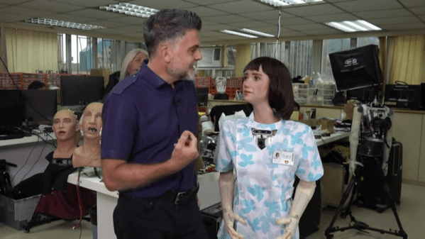
Hanson robotics wants to make robots, but not “Lost in Space” [Robby] robots. Think more [Data] from Star Trek robots. They’ve announced [Grace], a lifelike robot made to take on nursing duties for doctors and the elderly. In conjunction with Singularity Studio, the robot resembles the company’s [Sophia] robot which is made to be as realistic as possible given current technology and, apparently, has Saudi citizenship.
The robot has heat-sensitive cameras and other sensors so it can read data from patients directly. It uses the company’s Frubber for the face. The company says:
[Frubber is] a proprietary nanotech skin that mimics real human musculature and skin. This allows our robots to exhibit high-quality expressions and interactivity, simulating humanlike facial features and expressions.
Have you ever heard of a wigglegram? They are made by shooting multiple pictures at once using multiple lenses, and the the resulting stitched-together ‘gram is kind of a gif version of a stereographic image. It looks 3D, and it — well, it wiggles. The ones with a boomerang effect (i.e. a good loop) are especially prized.
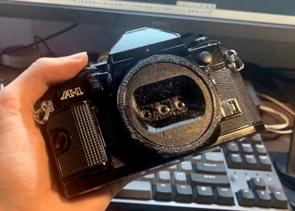
The only real drawback is that the camera has to be close to the subject because the three lenses are so tightly packed. Another drawback is that there is no viewfinder while using this lens. There have to be divider walls between the three lenses to keep the images separate, and these walls have to extend all the way into the camera body. The Canon A-1’s viewfinder mirror does not allow for this, so [Joshua] pushed it up out of the way.
[Joshua]’s initial design approach to finding the ideal lens distance from the film plane was to do a bunch of calculations, but he ended up Goldilocks-ing it and iterating a bunch of times until it was just right. If you have a Canon SLR and want to build one of these, you’re in luck as far as the STLs go.
Since 1996 the Pokemon series of games has moved through eight distinct generations, which roughly parallel the lineage of Nintendo’s handheld gaming systems. While the roster of “pocket monsters” has been updated steadily, players have had the option of bringing captured Pokemon from the older games into the newer releases. But there’s always been a gap in this capability. Due to hardware differences, the Game Boy and Game Boy Color generations of games were physically unable to communicate with the titles released for the Game Boy Advance.
But soon, that may no longer be the case. [Selim] is hard at work on Lanette’s Poke Transporter, a hardware and software solution for bringing Pokemon from the first and second generation games onto the third generation GBA games. Once they’ve been loaded there, players can move the creatures all the way up into the contemporary Pokemon games via official means.
The first Pokemon to make the generational leap.
The project was started in July of 2020, with [Selim] first focusing on the logistical challenges of bringing such early Pokemon into the newer games. Because so much changed between the different generations, there are many sanity checks that need to be made during the transfer. For example, the moves and techniques that the creatures are able to learn isn’t necessarily consistent between these early entries into the series. But after about a year of effort, the software side worked reliably on emulated games, and it was time to start thinking about the hardware.
Ultimately, [Selim] wants to create a physical device into which players can insert their Pokemon cartridges and trigger an automatic transfer. The code is already able to read and write to the cartridges, and has been ported over to Arduino so it doesn’t need a computer to run. A few prototype PCBs have been created, and beyond the inevitable bodges, it seems like they’re functional. There’s still breadboards and jumpers for as far as the eye can see, but this is the first step towards producing a dedicated Pokemon “time machine” that can transport them from the late 1990s to the present day.
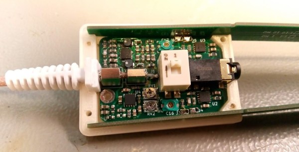
[Petteri Aimonen] presents for us a modular differential probe, as his entry into the 2021 Hackaday Prize.
This project shows a simple and well polished implementation of a differential-to-single-ended preamplifier, which allows a differential signal to be probed and fed to an oscilloscope via a BNC cable.
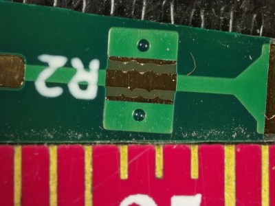
PCB Spark gap for primary ESD protection
It implements a classic instrumentation amplifier, where we have two amplifier stages. The first gives us the options for a gain of either 1 or 10, if we need it, with the second stage having a gain of 2.
The remaining circuit is a power supply to generate the necessary dual-rail supplies to feed the opamps. There is a lot of filtering on those output rails as well as on the USB power input side to try keep all that switched-mode power supply noise out of the signal path.
There are a couple of interesting design choices including the use of PCB material for the long removable probe arms, that integrate PCB spark gaps to offer a first defence against ESD reaching the more delicate parts of the system.
Why This Is Useful
There are two main classes of signals we electronics engineers care about: single-ended and differential-mode.
With the first kind, the signal is carried on a single wire, which is defined as being referenced to the common system ground. Current flows along the wire and returns to its source along the path of least resistance, at least at low frequencies. At higher frequencies, the path of least inductance is more relevant. This is all well and good, so long as you design the PCB correctly.
Coupling from adjacent wires due to mutual capacitance and inductance, as well as noise in the reference ground all conspire to mangle the signal we want to pass down the wire.
As the frequencies increase, and especially if you’re dealing with sharp edges, with all that extra odd-harmonic power, things start to get bad real fast. The way we deal with this is by utilising differential-mode signalling. This is where instead of a single wire, referenced to some notion of ground, we send the signal down a pair of wires, where the voltage difference between the wires forms the signal. Any external noise that leaks into the pair, will (hopefully!) affect both wires equally, forming what we call a common-mode component. When you look at the difference, this common mode noise disappears. (Our own [Bil Herd] covered this some time ago.)
When probing a circuit, it pays to have the right kind of probe as well as an understanding of the effect the probe will have on the circuit in operation. If you have a single-ended signal and you want to view it on your scope, your choice is either a passive or active probe. Usually some kind of passive probe will be most available. These commonly come in 50 Ω and 1 MΩ versions, and you need to be careful to use the correct probe type for your application.
For probing differential signals, it is possible to use a pair of probes, one for each signal wire, and then utilise the scope’s math difference function to show the signal. This is quite often a desperate measure, and what you really want is a differential front-end in hardware. You need a differential active probe.
The circuit may be simple, but don’t underestimate how much tweaking it needs to have good performance – a little slip with the PCB layout, as the author describes, caused some annoying resonances which can be hard to track down.
The project is still under active development, with the author showing the process as the project progresses, but its looking pretty good already, if you ask us.
Sources can found on his GitHib, which uses all Open Source tools, so its pretty accessible too.
Computers in working order and with correct software don’t make mistakes. People, however, make plenty of mistakes (including writing bad software or breaking computers). In quality circles, there’s a Japanese term, poka yoke, which roughly means ‘error avoidance’. The idea is to avoid errors by making them too obvious for them to occur. For example, consider a SIM card in your phone. The little diagonal corner means it only goes in one way. If you put it in the wrong way, it is obviously wrong.
To be successful at poka yoke, you have to be able to imagine what a user might do wrong and then come up with some way to make it obvious that it is wrong. There are examples of this all around us and we sometimes don’t even know it. For example, what do your credit card number, your car’s VIN code, and a UPC code on a can of beans have in common?
[Vintage Backyard RC] has built a nice little RC track in his backyard, and wanted a motorized dolly system to capture footage along the main straight with his GoPro. Using only junk box parts, he created a simple pedal operated RC cable dolly. (Video, embedded below.)
[Vintage Backyard RC] first experimented with a high speed car running on a length of model train track. However, it was bumpy at high speed, the track is expensive, and it needs 50 V running through the open tracks. The new cable cam gives a much smoother ride, and cost almost nothing with his supply of old RC gear. The cable cam is powered by a brushed motor from an RC airplane, running with plastic wheels on some weed trimmer line. Control is provided by an old 27 MHz RC system, with the controller’s internals transplanted into an old wah-wah guitar pedal.
The non-geared motor can drive the cable much faster than required, so [Vintage Backyard RC] needs to exercise some careful foot control to run it at a reasonable speed. This is easier said than done while also controlling an RC car with his hands, so he plans to replace the RC system with a newer 2.4 GHz system software end-point limits. We would be reaching for the ESP32 or any other microcontroller with wireless that we’ve come to know, but it’s worth remembering that most people are not familiar with these tools.