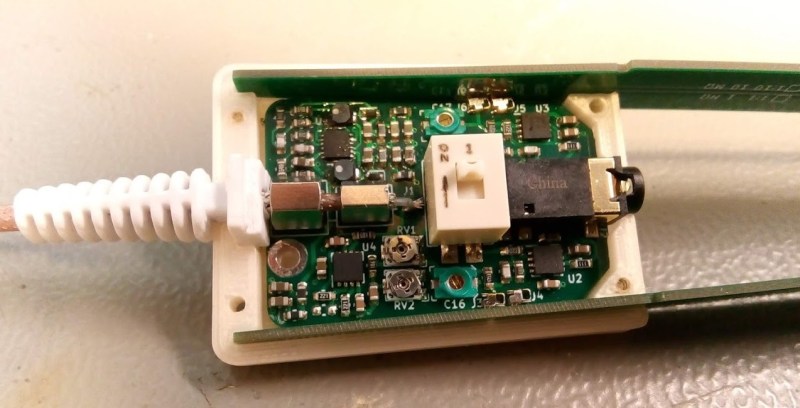
[Petteri Aimonen] presents for us a modular differential probe, as his entry into the 2021 Hackaday Prize.
This project shows a simple and well polished implementation of a differential-to-single-ended preamplifier, which allows a differential signal to be probed and fed to an oscilloscope via a BNC cable.
It implements a classic instrumentation amplifier, where we have two amplifier stages. The first gives us the options for a gain of either 1 or 10, if we need it, with the second stage having a gain of 2.
The remaining circuit is a power supply to generate the necessary dual-rail supplies to feed the opamps. There is a lot of filtering on those output rails as well as on the USB power input side to try keep all that switched-mode power supply noise out of the signal path.
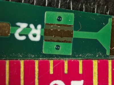
There are a couple of interesting design choices including the use of PCB material for the long removable probe arms, that integrate PCB spark gaps to offer a first defence against ESD reaching the more delicate parts of the system.
Why This Is Useful
There are two main classes of signals we electronics engineers care about: single-ended and differential-mode.
With the first kind, the signal is carried on a single wire, which is defined as being referenced to the common system ground. Current flows along the wire and returns to its source along the path of least resistance, at least at low frequencies. At higher frequencies, the path of least inductance is more relevant. This is all well and good, so long as you design the PCB correctly.
Coupling from adjacent wires due to mutual capacitance and inductance, as well as noise in the reference ground all conspire to mangle the signal we want to pass down the wire.
As the frequencies increase, and especially if you’re dealing with sharp edges, with all that extra odd-harmonic power, things start to get bad real fast. The way we deal with this is by utilising differential-mode signalling. This is where instead of a single wire, referenced to some notion of ground, we send the signal down a pair of wires, where the voltage difference between the wires forms the signal. Any external noise that leaks into the pair, will (hopefully!) affect both wires equally, forming what we call a common-mode component. When you look at the difference, this common mode noise disappears. (Our own [Bil Herd] covered this some time ago.)
When probing a circuit, it pays to have the right kind of probe as well as an understanding of the effect the probe will have on the circuit in operation. If you have a single-ended signal and you want to view it on your scope, your choice is either a passive or active probe. Usually some kind of passive probe will be most available. These commonly come in 50 Ω and 1 MΩ versions, and you need to be careful to use the correct probe type for your application.
For probing differential signals, it is possible to use a pair of probes, one for each signal wire, and then utilise the scope’s math difference function to show the signal. This is quite often a desperate measure, and what you really want is a differential front-end in hardware. You need a differential active probe.
The circuit may be simple, but don’t underestimate how much tweaking it needs to have good performance – a little slip with the PCB layout, as the author describes, caused some annoying resonances which can be hard to track down.
The project is still under active development, with the author showing the process as the project progresses, but its looking pretty good already, if you ask us.
Sources can found on his GitHib, which uses all Open Source tools, so its pretty accessible too.


Umm… we need this why? There are at least two channels, A and B, on an oscilloscope. Certainly on an oscilloscope capable of 100 MHz. So just invert channel B then enable A + B mode. Voila, a built-in differential input.
But you will use both channels for one signal and the substraction is done after the ADC (8 bits, at least on my Rigol) so it’s not perfect.
A (cheap) differential 10:1 probe is something really useful to have.
I use RS485 (modbus) with VFDs for commercial applications. I can’t reliably trigger off the noisy lines, so even though i can float the ground and do the subtraction of channel A and B to get the clean signal for decoding, the triggering is sketchy at best (10-20V amplitude HF noise from the VFD with 5V differential signal). If my scope could trigger of the math channel, that would be fine, but the hardware triggers dont work on the software math channel.
I was looking to build this one: https://hackaday.io/project/169390-a-10x-100mhz-differential-probe but the opamp is currently vaporware with the chip shortage…
Differential probes exist for important reasons apart from saving on a channel. They can be a lifesaver for getting accurate low amplitude and/or high frequency signals.
I actually started researching differential probes after I got annoyed with trying to do things with the subtraction trick when measuring the phase currents and voltages for a BLDC project.
At least my Rigol DS1054Z has severe limitations: for example, it cannot trigger based on the subtracted signal, the subtracted signal updates slower than other waveforms, the subtraction is 8-bit digital so it is impossible to see small signals on top of a large common mode voltage.
This is it right here. Imagine you want the 0.1 V ripple on a 20 V signal.
Subtracting the post-ADC values from each other is super noisy, b/c all of the bit resolution is wasted on spanning the range up to 20 V. If you only have an 8-bit scope, that’s discrete steps of 78 mV per step. You’ve got one bit of resolution on your noise signal.
If instead you subtract before ADC and scaling, you can put the whole bit-depth to work.
Jumping through flaming hoops of fire trying to quiet down power rails that are fed directly from a +/- SMPS. Nah… a much better way is to use the +/- SMPS as a pre-regulator then add a pair of +/- linear post-regulators in series. The PSRR of linear regulators is typically very high (e.g. 60 dB).
Agreed. This is what I would do if I were designing this. It is not at all trivial to make quiet power supplies. But the project is a great start, and this is something that could go in the next revision.
Alfred Rosenkränzer published some differential probe designs (even up to 1.9GHz) in Elektor Magazine that use LDOs to get good PSRR.
Thanks for the mention! I had not seen those before.
Looks like his 3/2017 version uses two stages of filtering: first 10 µH + 1 µF LC-filter, and then LT1962/LT1964 linear regulators. The MAX1697 charge pump that is used to generate negative rail operates at 250 kHz, and the use of LDOs is certainly a good choice to eliminate noise at those frequencies.
Because of the higher 1.4 MHz operating frequency of R1283 and the use of higher capacitance 10 µF MLCCs, I don’t have much low frequency noise to begin with.
Having some basic filtering followed by a linear regulator is the key to low noise SMPS designs, eats into efficiency a little, but for analog applications it is worth it by far.
For applications concerned with efficiency, then more filtering is a decent solution. Especially if one only needs 1 constant output voltage, then a bunch of caps can do wonders. Downside is that it takes a lot more room compared to a linear regulator, but can handle way more power for the same envelop in most cases.
For a differential probe like this that likely doesn’t consume above a few tens of mA, then a post regulator would have been a logical solution compared to tossing in tons of filtering.
Most noise in this case is at high frequencies, while LDOs rarely filter much beyond 10 MHz.
But it is an interesting consideration and I had not verified my assumptions on the topic, so I made a couple of measurements just now: https://hackaday.io/project/181065-modular-differential-probe/log/197133-power-supply-filtering
What about using something like a LM27762 for your split supply – it includes the LDOs on board. I’m working on an instrument myswlf, but am still at the design stage, so I’d be interested in the tradeoffs?
That is an interesting looking part, and also quite cheap (though unavailable currently). It is hard to say anything about its high-frequency performance because the specs only go up to 100 kHz (which is weird, considering it itself operates at 2 MHz). It also claims quite good efficiency for a charge-pump. In general charge pumps are less efficient and have larger current spikes than inductor based converters.