Simple IR Bounce Tachometer

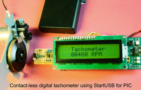
[Rajendra Bhatt] writes in to let us know about a nice simple IR bounce tachometer. The project uses a startUSB for PIC board and a 16×2 character LCD with a very basic Infrared bounce circuit.  Measuring either a reflective or non reflective spot in the rotating object, in this case a bit of white paper, the micro is supposedly capable of measuring up to 99,960 RPM (we think the paper might fly off at this point) with a resolution of 60 RPM. This is the same concept as a beam-break style tachometer but keeps all your electronics on one end of the spinning hazard.

The article also goes into detail about setting the PIC18F2550’s Timer0 register to enable 16-bit resolution.  The PIC is configured to turn on the infrared LED for one second, measure the number of pulses (through timer registers), and multiply that value by 60.  We would be more careful with the TMR0H and TMR0L counters as they have to be read and written in a certain order to preserve their values, but you’d need to be measuring upwards of 15,360 rpm to run into that error.

It is a quality writeup for anyone interested in learning about the start USB for PIC board, tachometers, or a new project. Thanks [Raj]!

Nerf Mind Bullets

[Chris] thinks that using your brain to control your trigger finger is a passé way of operating a toy firearm. Instead, he’s using his mind to fire foam bullets at whatever he thinks needs to pretend-die. To read his will, he’s chosen the Neurosky MindWave, a device that we just looked at for servo control. That hack shows how to patch into the USB dongle that comes with the device, but [Chris] opted to use a BlueSMiRF module from Sparkfun to connect the headset to an Arduino via Bluetooth.

The rest of the hack involves modifying the gun for automatic firing. It’s a Nerf Stampede, which takes six D-cells to power the electrical firing system. [Chris] didn’t want to carry that weight around in the body of the weapon itself so he installed a port for external power and added a firing mechanism at the same time. It uses relays to complete the circuit normally operated by the trigger. Now logic-level signals have no problem dispensing justice from the brightly-colored device.

[via Make]

DSLR Infrared Camera Conversion

ir_conversion

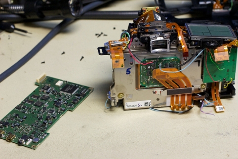
[Jerry] recently got a shiny new DSLR camera and was looking to do something with the old Pentax DSLR it replaced. Having performed a few point and shoot IR conversions in the past, he was pretty confident he could tackle this conversion without too much trouble.

He located the service manual for the camera and got busy taking it apart. He had to desolder the main board to get to the CCD block, where the sensor, IR cut filter, and the shake reduction motors are all located. The IR cut filter was pried off without too much trouble as it is only secured with a clip and an adhesive foam gasket.

Once things were disassembled, the real work began. He had a little trouble cutting the IR filter he purchased, so it took a little bit of elbow grease to get things exactly the way he wanted. Once he got the filter in place, he carefully re-mounted the sensor block to ensure that it was set at the proper height.

Once things were fully reassembled, he tried taking a few test shots, but found that there were some focus issues due to the IR filter being thicker than the original IR cut filter. A few manual tweaks in the camera’s debug menu and he was in business.

Be sure to check out his photo stream to take a look at some of the pictures he snapped with his new IR camera.

Relay Calculator

Calculators are a handy tool to have around in just about every application. We often take them for granted today, but even when I was a kid they were still sort of expensive devices that you put thought into buying. Illustrating just how far we have come is this awesome Relay Calculator brought to us by [Team 619].

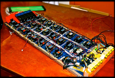
Featuring an optical slider input system, the user can select any two 4 bit numbers and can add or subtract them. Logic is carried out by a couple handfuls of relays setup to be AND, OR, or XOR gates, which are then linked together to build adders.

Output is in binary as well, in the form of lights, though we cant really tell if those are some form of tubes or if they are just rods lit on end. Either way if you require a lot of nibble math and want a conversation starter this suits the bill quite niceley. Otherwise you can keep hooking up more and more relays and maybe one day make your own relay computer.

Join us after the break for a quick video!

Continue reading “Relay Calculator”

Beat707 Takes It’s Cue From A Vintage Drum Machine

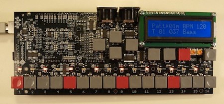
We always like musical hacks at hackaday, so we were pleased to see the team at [Beat707] come out with their Beat707 MIDI groove box.

The Beat707 takes it’s inspiration from the venerable Roland TR-707. Like the Roland, the Beat707 can save songs and has MIDI In and Out. Unlike the TR-707, the Beat707 doesn’t have an audio out – it’s purely MIDI based. Don’t think of that as a drawback, though. Just connect the Beat707 to your favorite softsynth and start jamming out.

The Roland TR-707 was heavily used by acts like the Chemical Brothers, Aphex Twin, and the Cocteau Twins. Because of this history, the popularity of the TR-707 has exploded over the past few years, and getting a hold of a real TR-707 has been an expensive proposition. While rebuilds of vintage synths like [Ladyada]’s TB-303 clone, the x0xb0x have been around for a while, we’re pleased that more projects are paying their dues to the great music machines of the 1980s.  Do any hackaday readers want to tackle an 808 or 909 for their next project?

Video of the Beat707 after the break.

Continue reading “Beat707 Takes It’s Cue From A Vintage Drum Machine”

Rule Your Furnace With This Network-enabled Thermostat

diy_thermostat

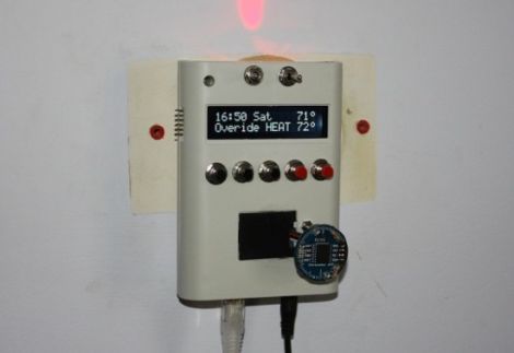
Adafruit forum member [Stephanie] embarked on a mission to replace the thermostat in her home with one that was far more robust and full of electronic goodies.

Her goal was to build a networked thermostat that allowed for 2-way communications between the base station and any other networked device, such as her laptop or iPhone. She wanted to not only be able to monitor her furnace and air conditioning systems remotely, but to control the units from afar as well.

The brains of the thermostat have changed throughout the project, becoming simpler as time went on. It is now controlled with just an ATMega328 mounted to the back of an LCD display with a Wiznet network module where an Adafruit Ethernet shield used to reside. The thermostat shows the current temperature, set temperature, and time on the front mounted LCD, the latter of which is provided by a Chronodot module. It also has an on board LED that can be seen from afar, indicating whether the heat or air conditioning is running,

Right now the thermostat can be controlled at the unit itself, or remotely using a Telnet session. [Stephanie] is currently happy with the setup, but future plans include creating an iPad application to provide a more user-friendly interface.

If you are interested in learning more, or building one yourself, be sure to swing by her blog for a far more in-depth look at the build process.

PCB Milling Tutorial

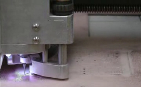
[Juan Jose Chong] put together a set of videos and a PDF guide to milling printed circuit boards. You’ll find the pair of videos, totaling about twenty-two minutes, embedded after the break. In them, [Jaun] details the techniques used by the IEEE chapter at Texas Tech University to mill PCBs instead of using the traditional method of etching them. We’ve long been a fan of milled PCBs and often dream about the day we can retire the old iron we use for the toner transfer method.

In the tutorial, IsoPro is the software used to control the mill. The CAM files from a PCB design program are imported – they can come from many different programs including EagleCAD. A few setup steps let the operator configure the resolution necessary to mill the correct tolerance and from there the paths that outline each trace are calculated in software. In order to facilitate double-sided boards a reference hole is drilled in the copper clad board to accept a post on the mill table. Tape down the substrate with some foil tape, set the depth of the end mill bit, and let the machine do its thing. [Juan’s] video illustrates how quickly this can produce a rather complicated board, finishing in around 20 minutes.

Continue reading “PCB Milling Tutorial”