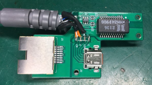
Pictures of the internals of the Starlink adapter

Restoring Starlink’s Missing Ethernet Ports

Internet connectivity in remote areas can be a challenge, but recently SpaceX’s Starlink has emerged as a viable solution for many spots on the globe — including the Ukrainian frontlines. Unfortunately, in 2021 Starlink released a new version of their hardware, cost-optimized to the point of losing some nice features such as the built-in Ethernet RJ45 (8P8C) port, and their proposed workaround has some fundamental problems to it. [Oleg Kutkov], known for fixing Starlink terminals in wartime conditions, has released three posts on investigating those problems and, in the end, bringing the RJ45 ports back.

Starlink now uses an SPX connector with a proprietary pinout that carries two Ethernet connections at once: one to the Dishy uplink, and another one for LAN, with only the Dishy uplink being used by default. If you want LAN Ethernet connectivity, they’d like you to buy an adapter that plugs in the middle of the Dishy-router connection. Not only is the adapter requirement a bother, especially in a country where shipping is impeded, the SPX connector is also seriously fragile and prone to a few disastrous failure modes, from moisture sensitivity to straight up bad factory soldering.

Continue reading “Restoring Starlink’s Missing Ethernet Ports”

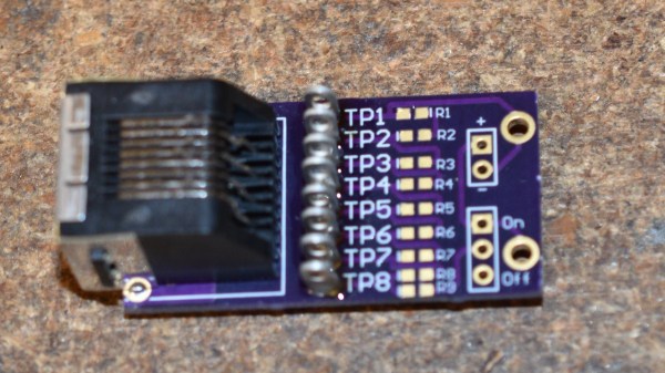
Receiver board of the Ethernet tester, with only probing pins, and no resistors populated

Ethernet Tester Needs No LEDs, Only Your Multimeter

Ethernet cable testers are dime a dozen, but none of them are as elegant and multimeter-friendly as this tester from our Hackaday.io regular, [Bharbour]. An Ethernet cable has 8 wires, and the 9 volts of easily available batteries come awfully close to that – which is why the board has a voltage divider! On the ‘sender’ end, you just plug this board onto the connector, powered by a 9 volt battery. On the “receiver” end, you take your multimeter out and measure the testpoints – TP7 should be at seven volts, TP3 at three volts, and so on.

As a result, you can easily check any of the individual wires, as opposed to many testers which only test pair-by-pair. This also helps you detect crossover and miswired cables – while firmly keeping you in the realm of real-life pin numbers! This tester is well thought-out when it comes to being easily reproducible – the PCB files are available in the “Files” section, and since the “receiver” and “sender” PCBs are identical, you only need to do a single “three PCBs” order from OSHPark in order to build your own!

Bharbour has a rich library of projects, and we encourage you to check them out! If you ever want to get yourself up to speed on Ethernet basics, we’ve talked about its entire history – and we’ve even explained PoE! After some intensive learning time, perhaps you can try your hand at crimping the shortest Ethernet cable ever.

Cat5 Camera Flash Extension

extension

Network engineer [Mario Giambanco] recently purchased a cable to move his flash off camera. Unfortunately, it ended up way too short for his purposes. Instead of purchasing a slightly longer proprietary cable, he decided to employ what he had around him: a lot of cat5e cable and ethernet jacks. He cut the cable close to the center in case things didn’t work out and he’d need to repair it. His post on building the custom ethernet flash extension cable goes into heavy detail to make sure you get it right the first time. He’s tested it using both five and 50 foot pieces of cable with no apparent lag.

This isn’t the first time we’ve seen cat5 repurposed: composite video through cat5, vga cat5 extension, and cat5 speaker cables.

[via Lifehacker]