Zero Parts-Count Temperature Sensor

Quick: What’s the forward voltage drop on a conducting diode? If you answered something like 0.6 to 0.7 V, you get a passing grade, but you’re going to have to read on. If you answered V_F = \frac{T-T_0}{k} where T0 and k are device-specific constants to be determined experimentally, you get a gold Jolly Wrencher.
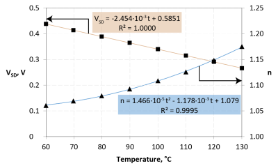
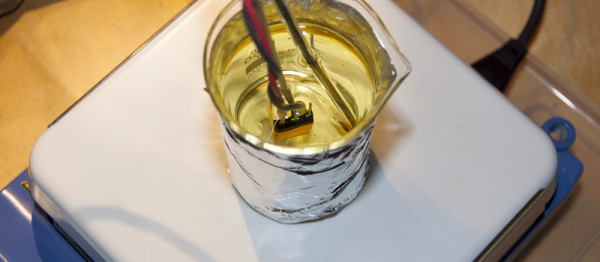
vsd%2C+n-01[Jakub] earned his Wrencher, and then some. Because not only did he use the above equation to make a temperature sensor, he did so with a diode that you might have even forgotten that you have on hand — the one inside the silicon of a MOSFET — the intrinsic body diode.

[Jakub]’s main project is an Arduino-controlled electronic load that he calls the MightWatt, and a beefy power MOSFET is used as the variable resistance element. When it’s pulling 20 or 30 A, it gets hot. How hot exactly is hard to measure without a temperature sensor, and the best possible temperature sensor would be one that was built into the MOSFET’s die itself.

There’s a bunch of detail in his write-up about how he switches the load in and out to measure the forward drop, and how he calibrates the whole thing. It’s technical, but give it a read, it’s good stuff. This is a great trick to have up your sleeve.

And if you’re in the mood for more stupid diode tricks, we recommend using them as solar cells or just stringing a bunch of them together to make a thermal camera.

Why 100 Watt EBay LEDs Are Not Your Friends

LEDs are amazing things. As time marches on, they are being used in more and more lighting applications – everything from household bulbs to automotive headlights. But the push for smaller, cheaper, and brighter LEDs seems to have hit a snag for some of the less reputable manufactures.

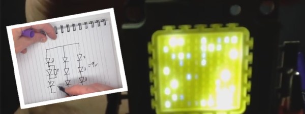
Case in point, [bigclivedotcom] has been testing of some 100 Watt LEDs from eBay. When these LEDs work correctly, they put out a face-melting beam of light that you wouldn’t dare looking into (picture the scene from Raiders of the Lost Ark). They also have some unusual specs for an LED, like running on 30 Volts – and that’s a lot compared to the forward voltage of most LEDs at around 2.5 volts@20 mA.

So what gives? Well many of these high-wattage LEDs use a string of several LEDs in series. And as [bigclivedotcom] points out, this can be a real problem when a few of the LEDs begin to fail and act more like a low value resistor than a typical LED. In the videos after the break you can see [bigclivedotcom] test the LEDs to get a better look and what’s happening and why.

Continue reading “Why 100 Watt EBay LEDs Are Not Your Friends”

Papercraft Dial Is The Slide-ruler Of Current Limiting Resistors

led_resistor_dial_39

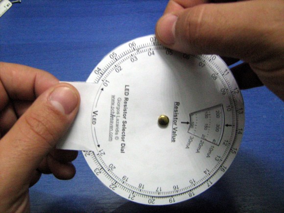
This paper dial makes selecting current limiting resistors a snap. [Giorgos Lazaridis] came up with the tool, which he describes in detail in the Worklog tab of his writeup. If you want one of your own he also posted a PDF which you can print, cut, and tack together.

At this point we can calculate resistor values for LED circuits without looking at reference material. But it wasn’t always like that. This wheel will be a fantastic tool for those just starting out in hobby electronics who are trying to grasp the theory behind lighting up a simple project. The outer wheel references the source voltage, with the inner being a gauge of forward voltage across the LED(s). Line those two values up and you can read the optimal resistor value in the window seen to the right. But wait, there’s more! As you can see in the video after the break the opposite face of the dial also includes a window which will tell you the power dissipation so that you may choose a properly rated resistor. Slick!

Continue reading “Papercraft Dial Is The Slide-ruler Of Current Limiting Resistors”

Reading Diodes To Create A Thermal Imaging System

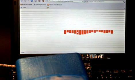
[Udo Klein] was working with some 1N4148 transistors and was interested in the specs relating to their performance at different temperatures. The forward voltage actually changes quite a bit depending on temperature and wondered if this could be reliably measured. He hacked his own LED shield for the Arduino to use as a 1×20 thermal imaging system.

The screenshot above is mapping the voltage measurements from a row of diodes (see the video after the break to get the full picture). He’s holding an ice pack over the row of diodes and observing the change. The on-screen display is facilitated by a Python script which is pulling data from the Arduino. Since there aren’t enough analog inputs to read all twenty diodes separately they have been multiplexed. Four I/O pins each enable five of the diodes, readings are taken with five analog inputs before moving on to the next set.

What can this be used for? That is precisely the wrong question… sometimes you’ve just got to go where your curiosity takes you. Continue reading “Reading Diodes To Create A Thermal Imaging System”