Last semester, [Peter], [Jared], and [Jeremy] took a course on embedded systems. They managed to turn out a very accurate copy of the classic Space Invaders in their class. Not wanting good code to go to waste, they decided to develop two player Space Invaders, and we wouldn’t mind testing it out.
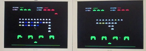
The guys built their Space Invaders clone on a Virtex II dev board. Wanting a little more hardware development, they picked up a pair of RF trancievers so the two boards could communicate with each other. The rules of two-player Space Invaders is fairly simple; if you destroy an alien, there’s a 30% chance it will appear on your opponent’s screen. Hit the space ship that flies along the top of the screen, and 1 to 7 aliens will appear on the opponent’s screen. It’s a bit like two player Tetris where your victories bring about your friend’s downfall.
The guys put a really neat spin on an old game, and we’d love to try it out. Check out the guy on the left losing a game of Space Invaders to his lab partner after the break.